
HP ProLiant BladeSystem p-Class System Maintenance and Service Guide


Connectors, LEDs, and Switches 86
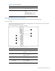
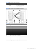
Table 4-19 RJ-45 Patch Panel LEDs
Item LED Description Status
1 Network link Amber = Network link
Off = No network link
2 Network activity/server blade presence Green (with no cable) = Server blade
present
Green (with cable) = Server blade
present and no activity
Green flashing = Network activity
Off = Server blade not present
GbE and GbE2 Interconnect Switches
Each interconnect switch has LEDs to indicate connectivity, speed, and management functions.
Front Panel LEDs
Use Figure 4-22 through Figure 4-27 and Table 4-20 through Table 4-25 to identify interconnect switch front panel
LED locations, assignments, and functions.
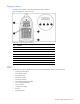
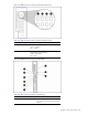
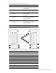
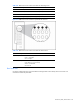
Figure 4-22 GbE Interconnect Switch front panel LEDs
Table 4-20 GbE Interconnect Switch Front Panel LEDs
Item LED Description Status
1 NIC Link activity and speed LEDs Refer to Figure 4-23, Figure 4-24, Table 4-21,
and Table 4-22 for NIC LED assignments and
functions.
2 Power status LED Green = Power on
Amber = Stand-by mode
Off = Power off
3 Management status LED Flashing = Management session active
Off = No management session active
4 Front panel RJ-45 connector link
speed LEDs
Amber = 1000 Mbps
Green = 100 Mbps
Off = No link