
HP ProLiant BladeSystem p-Class System Maintenance and Service Guide


Connectors, LEDs, and Switches 72
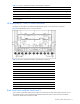
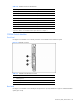
Figure 4-4 and Table 4-3 identify the patch panel RJ-45 connectors corresponding to the BL20p G2 server blade
network adapter Ethernet signals.
Figure 4-4 Patch panel RJ-45 connectors for the BL20p G2 server blade
Table 4-3 Patch Panel RJ-45 Connectors for the BL20p G2 Server Blade
Item Enclosure Enclosure with Enhanced Backplanes
D1–D8 iLO 10/100T NIC Not used
1
C1–C8 NC7781 10/100/1000T data NIC NC7781 10/100/1000T data NIC
B1–B8 NC7781 10/100/1000T data NIC 2 NC7781 10/100/1000T data NIC
2
A1–A8 NC7781 10/100/1000T data NIC NC7781 10/100/1000T data NIC
1
ILO connections are made through the iLO port on the server blade management module.
2
This is the default enabled PXE NIC. Using the ROM setup utility on the server, any other data NIC may be PXE enabled.
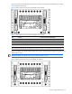
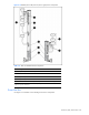
Figure 4-5 and Table 4-4 indicate the patch panel RJ-45 connectors corresponding to the BL30p server blade network
adapter Ethernet signals.
IMPORTANT: BL30p server blades require the enhanced server blade enclosure.
Figure 4-5 Patch panel RJ-45 connectors for the BL30p server blades