
HP ProLiant BL p-Class System Setup and Installation Guide
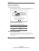

LEDs and Switches
HP ProLiant BL p-Class System Setup and Installation Guide D-11
HP CONFIDENTIAL
Writer: Christine Portillo File Name: i-appd LEDs and Switches.doc
Codename: ICE Part Number: 230852-002 Last Saved On: 11/20/02 5:00 PM
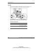
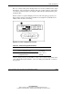
The zone 1 switch setting is the default position; it is used for scalable bus bar, single
mini bus bar, and power bus box solutions. The zone 2 switch setting is only used for
a secondary power zone when you configure a full-rack 42U solution with two pairs
of mini bus bars.
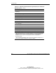
For the system to recognize multiple power zones and rack topology properly, you
must set these switches at the time of installation. Use Figure D-9 and Table D-9 to
identify switch locations and settings.
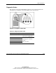
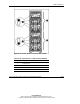
Figure D-9: Power configuration switches
Table D-9: Power Configuration Switches
Item Description Positions
1 Server blade management module
power configuration switch
2 Power management module power
configuration switch
Up = Zone 2
(secondary)
Down = Zone 1
(default)
After the initial power-up, use the LEDs to verify correct switch settings. Refer to the
“Server Blade Management Module” and “Power Management Module” sections in
this appendix.