
HP ProLiant BL p-Class System Setup and Installation Guide

Installing System Hardware
3-16 HP ProLiant BL p-Class System Setup and Installation Guide
HP CONFIDENTIAL
Writer: Christine Portillo File Name: d-ch3 Installing System Hardware.doc
Codename: ICE Part Number: 230852-002 Last Saved On: 11/20/02 4:54 PM
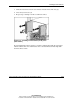
Power Distribution Components
The system requires components to distribute -48 VDC power from the power
enclosure or facility -48 VDC source to the server blade enclosures.
Installation Guidelines
Observe the following guidelines:
• Always be sure to set the rack rail depth for enclosures between 73.66 cm and
76.20 cm (29 inches and 30 inches) for proper bus bar clearance in a rack with a
rear rack door.
• Always be sure that power components are disconnected and that all circuit
breakers on bus bars and power enclosures are locked in the off position before
installing the bus bars. For circuit breaker locations, refer to Chapter 4, “Cabling
and Powering Up the System.”
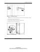
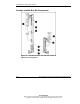
Installing a Bus Bar
1. Using the marks you made when measuring with the template, install the cage
nuts for hinges and the cable bracket, if you have not already done so.
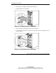
IMPORTANT: In AC power configurations, the bottom hinges for each bus bar are
installed into cage nuts and the ends of power enclosure rack rails. In these locations, the
rails have extrusions to align the hinges and holes to accept screws. In facility DC power
configurations, you must install cage nuts to support the bottom hinges.