
HP ProLiant BL p-Class System Diagnostic Station User Guide

For more information about installing hardware options and performing
troubleshooting procedures, refer to the p-Class server blade setup and installation
guides on the Documentation CD and to the documentation that ships with the
interconnect switch.
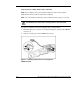
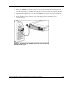
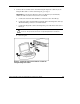
Diagnostic Station Components
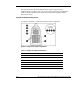
Use Figure 4 and Table 3 to identify diagnostic station components.
Figure 4: Diagnostic station components
Table 3: Diagnostic Station Components
Item Description
1 RJ-45 connector for NIC 1 (PXE default & Data)
2 RJ-45 connector for NIC 2 (Data)
3 RJ-45 connector for NIC 3 (Data)
4 RJ-45 connector for NIC 4 (iLO)
5 Reserved for additional AC power
6 AC power input connector
continued
12 HP ProLiant BL p-Class System Diagnostic Station User Guide
HP CONFIDENTIAL
Writer: Amy Clute File Name: 230859-3.doc
Codename: Nipper Part Number: 230859-003 Last Saved On: 9/10/03 8:46 AM