
HP ProLiant BL e-Class System Setup and Installation Guide


Installing and Cabling the System
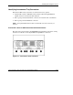
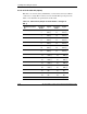
Table 3-2: RJ-21 Patch Panel Connectors
Item Description Location
1 RJ-21 connector for server blade bays 11-20 NIC 2 RJ-21 patch panel
2 RJ-21 connector for server blade bays 1-10 NIC 2 RJ-21 patch panel
3 Integrated Administrator management connector
(10/100 Ethernet)*
Integrated Administrator module
4 Integrated Administrator console connector (serial)* Integrated Administrator module
5 Enclosure link (RJ-45) connector—Reserved* Integrated Administrator module
6 Enclosure link (RJ-45) connector—Reserved* Integrated Administrator module
7 RJ-21 connector for server blade bays 11-20 NIC 1 RJ-21 patch panel
8 RJ-21 connector for server blade bays 1-10 NIC 1 RJ-21 patch panel
* These items denote connectors for the Integrated Administrator module.
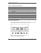
RJ-45 Patch Panel Connectors
The RJ-45 patch panel features two RJ-45 connectors for each server blade, for a
total of 40 RJ-45 connectors.
Figure 3-15: RJ-45 patch panel connectors
HP ProLiant BL e-Class System Setup and Installation Guide 3-17
HP CONFIDENTIAL
Writer: Karen Hale File Name: d-ch3 Installing and Cabling the System.doc
Codename: MacDuff Part Number: 249068-003 Last Saved On: 5/21/03 3:04 PM