
Installation and Getting Started Guide for ProCurve 2600 Switches 2008-01


2-24
Installing the Switch
Installation Procedures
Installing the Switch
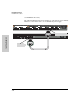
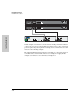
600 RPS/EPS Connectivity
The following illustration shows an example of connectivity between an RPS/
EPS device and a switch device as a redundant AC power supply.
Device Connected
Power Status
R1 R2 R3 R4 R5 R6 E1
Device
Connected
Pow er
Status
E2
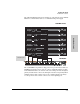
RPS 1 RPS 2 RPS 3 RPS 4 RPS 5 RPS 6 EPS 1 EPS 2
EPS Power: 50V 370W total for PoE applications. Power is shared when both ports are used.
RPS Power: 12V backup to one connected device. Lowest-numbered port has priority.
Line: 50/60 Hz.
10
0
-
2
40 V~ 9.1A (9,1A)
Console
!
Line 50/60 Hz.
100-240 V~ 7.5 A
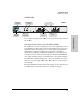
EPS Input
HP ProCurve
RPS Input
12V 7.5A
RPS input port
Switch RPS output port