
3Com Switch 7750 Configuration Guide


476 CHAPTER 47: PIM CONFIGURATION
PIM Configuration
Examples
PIM-DM Configuration
Example
Network requirements
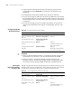
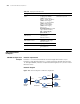
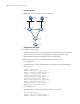
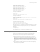
Lanswitch 1 is connected to Multicast Source through Vlan-interface 10, to
Lanswitch 2 through Vlan-interface 11 and to Lanswitch3 through Vlan-interface
12. Through PIM-DM, multicast is implemented among Receiver 1, Receiver 2 and
Multicast Source.
Network diagram
Figure 118 Network diagram for PIM-DM configuration
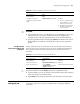
Table 383 Display and maintain PIM
Configuration Command Description
Display PIM multicast routing
tables
display pim routing-table
[{{*g [ group-address
[ mask { mask-length |
mask }]] | **rp [ rp-address
[ mask { mask-length |
mask }]]} |{group-address
[ mask { mask-length |
mask }] | source-address
[ mask { mask-length |
mask }]} * } |
incoming-interface { interfac
e-type interface-number |
null } | { dense-mode |
sparse-mode }] *
You can execute the display
command in any view.
Display the information about
PIM interfaces
display pim interface
[ interface-type
interface-number ]
Display the information about
PIM neighbor routers
display pim neighbor
[ interface interface-type
interface-number ]
Display BSR information display pim bsr-info
Display RP information display pim rp-info
[ group-address ]
Multicast
Sourse
VLAN 10
VLAN 12
VLAN 11
VLAN 20
VLAN 30
Lanswitch1
Lanswitch2
Lanswitch3
RECEIVER1
RECEIVER2