
3Com Switch 7750 Configuration Guide


IGMP Snooping Configuration Example 439
Configure Multicast
VLAN
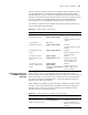
Network requirements
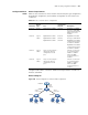
Table 351 lists all the devices in the network. Assume that port type configuration,
VLAN division configuration, and IP address configuration for the interface are
completed.
Configure VLAN 1024 as a multicast VLAN and configure VLAN 2 to VLAN 7 as
multicast sub-VLANs.
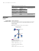
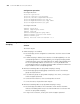
Network diagram
Figure 109 Network diagram for multicast VLAN configuration
Table 351 List of network device configurations
Device ID
Device
type Port
Device
connected to
the port Description
Router A Router GigabitEthernet 0/0/0 Switch B GigabitEthernet0/0/0
belongs to VLAN1024,
where the PIM-SM and
IGMP protocols are
enabled.
Switch B Layer 3
switch
GigabitEthernet 2/0/1
GigabitEthernet 2/0/2
GigabitEthernet 2/0/3
Router A
Switch C
Switch D
GigabitEthernet 2/0/1
belongs to VLAN 1024.
GigabitEthernet 2/0/2 is
a trunk port belonging
to VLAN 2 to VLAN 4.
GigabitEthernet 2/0/3 is
a trunk port belonging
to VLAN 5 to VLAN 7.
Switch C Layer 2
switch
The port connecting the
upper-layer switch is
configured as a trunk
port.
- Switch C is connected
to users belonging to
VLAN 2 to VLAN 4
where the IGMP
snooping function is
enabled.
Switch D Layer 2
switch
The port connecting the
upper-layer switch is
configured as a trunk
port.
- Switch C is connected
to users belonging to
VLAN 5 to VLAN 7
where the IGMP
snooping function is
enabled.
RouterA
SwitchB
SwitchC SwitchD
GE2/0/1
VLAN 1024
GE0/0/0
GE2/0/2
VLAN 2-VLAN 4
GE2/0/3
VLAN 5 -VLAN 7
HostC
(VLAN4)
HostB
(VLAN 3 )
HostA
(VLAN 2)
HostF
(VLAN 7)
HostE
(VLAN 6)
HostD
(VLAN 5 )