
3Com Switch 7750 Configuration Guide Guide
Configuration Example 357
[SwitchA-bgp] peer 192.1.1.2 group ex as-number 200
[SwitchA-bgp] network 1.0.0.0 255.0.0.0
2 Configure SwitchB.
# Configure VLAN2.
[SwitchB] interface Vlan-interface 2
[SwitchB-Vlan-interface2] ip address 192.1.1.2 255.255.255.0
# Configure VLAN3.
[SwitchB] interface Vlan-interface 3
[SwitchB-Vlan-interface3] ip address 193.1.1.2 255.255.255.0
# Configure a BGP peer.
[SwitchB] bgp 200
[SwitchB-bgp] group ex external
[SwitchB-bgp] peer 192.1.1.1 group ex as-number 100
[SwitchB-bgp] group in internal
[SwitchB-bgp] peer 193.1.1.1 group in
3 Configure SwitchC.
# Configure VLAN3.
[SwitchC] interface Vlan-interface 3
[SwitchC-Vlan-interface3] ip address 193.1.1.1 255.255.255.0
# Configure VLAN4.
[SwitchC] interface vlan-Interface 4
[SwitchC-Vlan-interface4] ip address 194.1.1.1 255.255.255.0
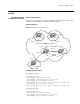
# Configure BGP peers and RR.
[SwitchC] bgp 200
[SwitchC-bgp] group rr internal
[SwitchC-bgp] peer rr reflect-client
[SwitchC-bgp] peer 193.1.1.2 group rr
[SwitchC-bgp] peer 194.1.1.2 group rr
4 Configure SwitchD.
# Configure VLAN4.
[SwitchD] interface vlan-interface 4
[SwitchD-Vlan-interface4] ip address 194.1.1.2 255.255.255.0
# Configure a BGP peer.
[SwitchD] bgp 200
[SwitchD-bgp] group in internal
[SwitchD-bgp] peer 194.1.1.1 group in
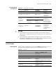
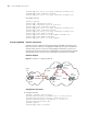
Use the display bgp routing-table command to display the BGP routing table on
SwitchB. Note that, SwitchB has already known the existence of network 1.0.0.0.
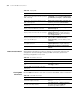
Use the display bgp routing-table command to display the BGP routing table on
SwitchD. Note that, SwitchD knows the existence of network 1.0.0.0, too.
Configuring BGP
Routing
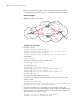
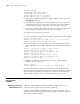
Network requirements
BGP is applied to all switches, and OSPF is applied to the IGP in AS200. SwitchA is
in AS100, and SwitchB, SwitchC, and SwitchD are in AS200. EBGP is running