
3Com Switch 4200G Configuration Guide


390 CHAPTER 45: CONFIGURATION OF NEWLY ADDED CLUSTER FUNCTIONS
Configuration
Example for Newly
Added Cluster
Functions
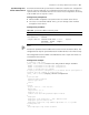
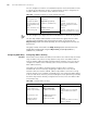
Network requirements In a cluster formed by Switch A, Switch B, Switch C, and Switch D, Switch A is the
master switch. NDP and NTDP configurations are performed on the related devices.
The cluster is enabled and you can manage member devices on the master device.
■ The IP address of the TFTP Server configured for the cluster is 10.1.1.15.
■ The IP address of the SNMP host configured for the cluster is 10.1.1.16.
■ Log into the Web page of the master switch and view the file on the Flash of a
member device.
■ Log into the Web page of the master switch and upgrade software.
■ Log in to the Web page of the master switch and restore the configuration.
■ Remove the member device numbered 3 from the cluster and add it to the black
list.
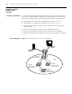
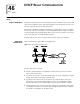
Network diagram Figure 122 Network diagram for HGMP cluster management
Sw itc h A
Management Device
SNMP host
10.1.1.16
Clus ter
TFTP server
10.1.1.15
E1/1 E1 /2
E1/1
E1/1
Sw itc h C
Me mber Dev ic e 2
00e0-fc01-0012
Sw itc h C
Member Device 3
00e0-fc01-0013
E1/10
E1/ 1
Sw itc h B
Member Device 2
00e0-fc01-0011
Sw itc h A
Management Device
SNMP host
10.1.1.16
Clus ter
TFTP server
10.1.1.15
E1/1 E1 /2
E1/1
E1/1
Sw itc h C
Me mber Dev ic e 2
00e0-fc01-0012
Sw itc h C
Member Device 3
00e0-fc01-0013
E1/10
E1/ 1
Sw itc h B
Member Device 2
00e0-fc01-0011