
3Com Switch 4200G Configuration Guide


114 CHAPTER 20: MSTP CONFIGURATION
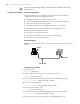
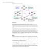
Figure 36 Basic MSTP terminologies
MST region
An MST region (multiple spanning tree region) comprises multiple
physically-interconnected MSTP-enabled switches and the corresponding network
segments connected to these switches. These switches have the same region name,
the same VLAN-to-spanning-tree mapping configuration and the same MSTP revision
level.
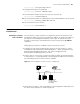
A switched network can contain multiple MST regions. You can group multiple
switches into one MST region by using the corresponding MSTP configuration
commands. For example, all switches in region A0 shown in Figure 36 have the same
MST region configuration: the same region name, the same VLAN-to-spanning-tree
mappings (that is, VLAN 1 is mapped to spanning tree instance 1, VLAN 2 is mapped
to spanning tree instance 2, and other VLANs are mapped to CIST), the same MSTP
revision level (not shown in Figure 36).
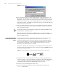
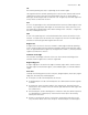
MSTI
A multiple spanning tree instance (MSTI) refers to a spanning tree in a MST region.
Multiple spanning trees can be established in one MST region. These spanning trees
are independent of each other. For example, each region in Figure 36 contains
multiple spanning trees known as MSTIs (multiple spanning tree instances). Each of
these spanning trees corresponds to a VLAN.
VLAN mapping table
A VLAN mapping table is a property of an MST region. It contains information about
how VLANs are mapped to MSTIs. For example, in Figure 36, the information
contained in the VLAN mapping table of region A0 is: VLAN 1 is mapped to MSTI 1;
VLAN 2 is mapped to MSTI 2; and other VLANs are mapped to CIST. In an MST region,
load balancing is achieved by the VLAN mapping table.