HP Power Protector User Guide Abstract This document includes installation, configuration, and operation information for HP Power Protector software. This document is for the person who installs and maintains power products. HP assumes you are qualified in the servicing of high-voltage equipment and trained in recognizing hazards in products with hazardous energy levels.
© Copyright 2011, 2013 Hewlett-Packard Development Company, L.P. The information contained herein is subject to change without notice. The only warranties for HP products and services are set forth in the express warranty statements accompanying such products and services. Nothing herein should be construed as constituting an additional warranty. HP shall not be liable for technical or editorial errors or omissions contained herein. Confidential computer software.
1 2 3 4 Redistributions of source code must retain the copyright notice, this list of conditions and the following disclaimer. Redistributions in binary form must reproduce the above copyright notice, this list of conditions and the following disclaimer in the documentation and/or other materials provided with the distribution.
Contents Overview ..................................................................................................................................... 7 Introduction .............................................................................................................................................. 7 Overview ................................................................................................................................................. 7 Architecture ..............................
Scheduled Shutdown screen............................................................................................................ 63 System screen ............................................................................................................................... 66 User Accounts screen ..................................................................................................................... 68 Views ..................................................................................
HPPP Clients do not appear on the HPPP Administrator Notified Application screen ....................................... 127 HPPP sends invalid links in email notifications on Linux platforms ................................................................. 127 Error occurs when starting the HPPP service on RHEL IA64 .......................................................................... 128 Invalid IP address ...............................................................................................
Overview Introduction HP Power Protector (HPPP) enables you to monitor, manage, and control power environments through comprehensive control of individual HP UPSs. A familiar browser interface provides secure access to HPPP anywhere on the network. You can control power failure settings to allow for maximum uptime of critical servers. For a detailed list of supported UPSs, see the Supported Hardware matrix on the HP website (http://www.hp.com/go/rackandpower).
be controlled independently. By shutting down a load segment that is connected to less critical equipment, the runtime for more critical equipment is extended, providing additional protection.
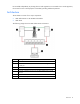
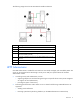
The following image shows the HP UPS Network Module architecture: Item Description 1 UPS with an HP UPS Network Module 2 HPPP Client server 3 Network 4 HP Systems Insight Manager receiving alert traps from the HP UPS Network Module (optional) 5 A remote workstation browsing into the HPPP Administrator over the network Green Power connection Red Communication path HPPP Administrator One HPPP Administrator is needed for each UPS that is monitored, managed, and controlled by HPPP.
o Performing operating system shutdown by notifying the HPPP Clients when to shut down o Shutting down and restarting by load segment, if applicable o Performing a UPS shutdown • Performing a graceful, remote shutdown of the local operating system after a specified delay • Maintaining event logs, which include the following types: • o UPS event log, which contains UPS-related events, such as the UPS going on battery o Application event log, which contains application-related events, such as fa
NOTE: For the latest supported operating systems, see the HP website (http://www.hp.com/go/rackandpower). Supported hardware configurations HPPP requires that the HPPP Administrator and the servers running the HPPP Clients are connected to the network. UPSs can be attached in any of the following configurations: • Configuration A (on page 11)—An HPPP Administrator is serially attached to one UPS.
Configuration B This figure illustrates one server as an HPPP Administrator and it is serially attached to the UPS. This HPPP Administrator communicates to the HPPP Client servers over the network to begin a graceful shutdown in the event of a power failure or other configured shutdown events. NOTE: Up to 35 HPPP Clients can be managed by one HPPP Administrator.
Configuration C This figure illustrates a UPS that is connected to the HPPP Administrator through a USB port. The HPPP Administrator is plugged into a load segment of the UPS and connected directly to the network. A remote workstation can browse into the HPPP Administrator over the network.
Item Description 1 UPS 2 HPPP Administrator 3 HPPP Client server 4 HPPP Client server 5 Network 6 Remote workstation browsing into the HPPP Administrator or Client over the network Green Power connection Red Communication path Black USB connection Configuration E This figure illustrates one or more HPPP Clients are powered by a UPS and communicates with one UPS Network Module over the network to begin a graceful shutdown in the event of a power failure or other configured shutdown events
Item Description 1 UPS with an HP UPS Network Module 2 HPPP Client server 3 HPPP Client server 4 HPPP Client server 5 Network 6 Remote workstation browsing into the HP UPS Network Module or HPPP Client over the network Green Power connection Red Communication path Configuration F This figure illustrates one or more HPPP Clients are redundantly powered by two UPSs and communicate with two UPS Network Modules over the network to begin a graceful shutdown in the event of a power failure or ot
Item Description 1 UPS with an HP UPS Network Module 2 UPS with an HP UPS Network Module 3 HPPP Client server 4 HPPP Client server 5 Network 6 Remote workstation browsing into the UPS Network Module or HPPP Client over the network Green Power connection Red Communication path Using the redundant configuration Before using a redundant configuration, verify the following: • HP UPS Network Modules and HPPP Clients are installed. • The two UPSs are the same model.
Setup overview To setup HPPP: 1. Visit the HP website (http://www.hp.com/go/rackandpower) to download the latest version of HPPP. 2. Connect all equipment powered by the UPS to the receptacles on the UPS rear panel. If the UPS has multiple load segments, note which load segment powers each device. 3. Power up the UPS and all attached equipment. 4. Be sure that the serial or USB cable connecting the UPS to the HPPP is properly installed. 5.
Installation System requirements For a complete list of supported operating systems, web browser requirements, and supported hardware, see the HP website (http://www.hp.com/go/rackandpower).
Installing HPPP on Windows operating systems HPPP can be installed using either a graphical installer or a silent installation on any supported Windows operating system. To ensure that your system meets the minimum requirements, see "System requirements (on page 18)." Installing HPPP using the GUI installer on Windows systems NOTE: Before installing the software, be sure that the serial or USB cable connecting the UPS to the server is properly installed. To install HPPP using the GUI installer: 1.
2. Verify that the device communication cables are connected, and then click Next. The Select Path screen appears. 3. Click Install to install HPPP in the default folder. To specify a different folder, click the folder icon, navigate to the appropriate folder, and then click Install.
The Finish screen appears. 4. Click Finish to launch the application. The End User License Agreement screen appears.
5. Read the license agreement, and then click Accept. 6. Log in to HPPP using the default credentials admin/admin, and then you are prompted to configure the Power Protector as Administrator or Client. The HP Power Protector Configuration screen appears. 7. Select the HPPP component that you are installing on this server, and then click Save.
Installing HPPP using the silent installation method on Windows systems NOTE: Before installing the software, be sure that the serial or USB cable connecting the UPS to the server is properly installed. During a silent installation, install an HPPP Administrator or Client through the assisted installation method that is appropriate for the operating system. From the directory that contains the .exe file, execute the file with the -silent argument. c:\hppp_win_1_00_011.
Native installation on a RedHat, SUSE, or derivative system To install HPPP using the Native installation method: 1. Double-click the HPPP .rpm package. The system prompts for the root password, and then launches a graphical front-end. 2. After the installation is complete, launch a supported browser. The browser window appears. 3.
where is the IP address of the server hosting HPPP. The End User License Agreement screen appears. 4. Log into HPPP using the default credentials admin/admin. The HP Power Protector Configuration screen appears. 5. Select the HPPP component that you are installing on this server, and then click Save.
Installing HPPP using the CLI on Linux systems NOTE: Before installing the software, be sure that the serial or USB cable connecting the UPS to the server is properly installed. Native installation on a RedHat, SUSE, or derivative system To install HPPP from a command line: 1. Execute the following command (as root): $ rpm -i hppp-linux_X.Y.Z.rpm 2. After the installation is complete, launch a supported browser. The browser window appears. 3.
where is the IP address of the server hosting HPPP. The End User License Agreement screen appears. 4. Log into HPPP using the default credentials admin/admin. The HP Power Protector Configuration screen appears. 5. Select the HPPP component that you are installing on this server, and then click Save.
If your system does not derive from RedHat (using .rpm), you can install HPPP using the Generic Package. To install HPPP from a command line: 1. Execute the following command from where the generic installer is located (as root): $ hppp-linux-x_yz-i386 -install 2. Verify that the device communication is connected, and then enter Y to proceed with the installation. 3. Press Enter to use the default installation path or enter the new installation path, and then press Enter. 4.
where is the IP address of the server hosting HPPP. The End User License Agreement screen appears. 7. Log into HPPP using the default credentials admin/admin. The HP Power Protector Configuration screen appears. 8. Select the HPPP component that you are installing on this server, and then click Save.
Installing HPPP using the silent installation method on Linux systems NOTE: Before installing the software, be sure that the serial or USB cable connecting the UPS to the server is properly installed. During a silent installation, install an HPPP Administrator or Client through the assisted installation method that is appropriate for the operating system. To install HPPP using the silent installation method: 1. Execute the file: hppp-linux-x_y_z-i386 -silent 2.
where is the IP address of the server hosting HPPP. The End User License Agreement screen appears. 4. Log into HPPP using the default credentials admin/admin. The HP Power Protector Configuration screen appears. 5. Select the HPPP component that you are installing on this server, and then click Save.
Uninstalling HPPP from Linux systems Native uninstallation on a RedHat, SUSE, or derivative system To uninstall HPPP from the command line, execute the following command: rpm –e hppp-linux Generic uninstallation To uninstall HPPP using the Generic Package: 1. From the command line, execute the following command: mc2 –uninstall For example: # /usr/local/HP/Power Protector/mc2 -uninstall 2. Enter Y to proceed with the uninstallation. 3.
Installing HPPP on HP-UX operating systems HPPP can be installed using the SAM or Generic Package installation option on any supported HP-UX operating system. To ensure that your system meets the minimum requirements, see "System requirements (on page 18)." Installing HPPP locally using the Generic Package method NOTE: Before installing the software, be sure that the serial cable connecting the UPS to the server is properly installed. To install HPPP using the Generic Package: 1.
where is the IP address of the server hosting HPPP. The End User License Agreement screen appears. 7. Log into HPPP using the default credentials admin/admin. The HP Power Protector Configuration screen appears. 8. Select the HPPP component that you are installing on this server, and then click Save.
Installing HPPP locally using the SAM method NOTE: Before installing the software, be sure that the serial cable connecting the UPS to the server is properly installed. To install HPPP using the SAM method: 1. From the SAM application, double-click Software Management. 2. Click Install Software to Local Host. 3. Change the Source Depot Path to a fully qualified path and depot name. 4. Select the HP Power Protector you are about to install. 5. Click Actions>Install from the top menu. 6.
where is the IP address of the server hosting HPPP. The End User License Agreement screen appears. 11. Log into HPPP using the default credentials admin/admin. The HP Power Protector Configuration screen appears. 12. Select the HPPP component that you are installing on this server, and then click Save.
Installing HPPP remotely using the Generic Package method NOTE: Before installing the software, be sure that the serial cable connecting the UPS to the server is properly installed. To install HPPP remotely using the Generic Package method: 1. Find the server on the network, and then log in as a super user. 2. Locate the HPPP package, and then from the command line execute the following command: ./hppp-hp-ux-x_y_z-ia64 –install 3.
where is the IP address of the server hosting HPPP. The End User License Agreement screen appears. 7. Log into HPPP using the default credentials admin/admin. The HP Power Protector Configuration screen appears. 8. Select the HPPP component that you are installing on this server, and then click Save.
Installing HPPP remotely using the SAM method NOTE: Before installing the software, be sure that the serial cable connecting the UPS to the server is properly installed. To install HPPP remotely using the SAM method: 1. From a remote machine, enter sam at the command line prompt. 2. Click Software Management. 3. Click Install Software to Local Host. 4. Change the Source Depot Path to a fully qualified path and depot name. 5. Select the HP Power Protector you are about to install. 6.
where is the IP address of the server hosting HPPP. The End User License Agreement screen appears. 12. Log into HPPP using the default credentials admin/admin. The HP Power Protector Configuration screen appears. 13. Select the HPPP component that you are installing on this server, and then click Save.
Installing HPPP using the silent installation method on HP-UX systems NOTE: Before installing the software, be sure that the serial cable connecting the UPS to the server is properly installed. During a silent installation, install an HPPP Administrator or Client through the assisted installation method that is appropriate for the operating system. To install HPPP using the silent installation method: 1. Locate the generic HPPP package and from the command line, execute the following command: .
where is the IP address of the server hosting HPPP. The End User License Agreement screen appears. 4. Log into HPPP using the default credentials admin/admin. The HP Power Protector Configuration screen appears. 5. Select the HPPP component that you are installing on this server, and then click Save.
Uninstalling HPPP from HP-UX systems To uninstall HPPP: 1. From the command line, execute the following command: mc2 –uninstall For example: # /opt/HP/HP Power Protector/mc2 -uninstall 2. Enter Y to proceed with the uninstallation. 3. Enter Y to remove all files created by the application. 4. Enter Y to confirm removing Power Protector. NOTE: Some files might remain following the uninstallation and can be removed manually.
Access and navigation Accessing the software You can access the software: • Remotely through a web browser (on page 44) • Locally from the Start menu in Windows Web browser To access HPPP through a web browser: 1. Launch a supported browser. The browser window appears. 2. In the URL field, enter an IP address. Use the following examples, where hostname is the IP address or the machine name of the computer on which HPPP is installed.
• Open the notification window • Open the web interface • Stop HPPP • Start HPPP To view the status of HPPP through the system tray icon, do one of the following: • Hover over the system tray icon on a computer with one of the software components installed. • Right-click the software system tray icon on a computer with one of the software components installed to display a context menu. Icon Status The power source is not configured. The HPPP service stopped.
When in redundant configuration, no power source information appears; only the Messages list appears. Browser security alert NOTE: The information in this section is only applicable if SSL is chosen during software configuration. Secure browsing requires the use of SSL. SSL is a protocol layer that lies between HTTP and TCP that provides secure communication between a server and a client and is designed to provide privacy and message integrity.
2. Verify that the name in the Issued To field is the name of your device. 3. Perform any other steps necessary to verify the identity of the device. CAUTION: If you are not sure this is the desired device, do not proceed. Importing a certificate from an unauthorized source relays your login credentials to that unauthorized source. Exit the certificate window and contact the system administrator. After verifying the device, do one of the following: • Import the certificate and proceed. a.
3. Perform any other steps necessary to verify the identity of the device. 4. After verifying the device, do one of the following: a. Click either Accept this certificate permanently or Accept this certificate temporarily for this session. b. Click OK. NOTE: If using Firefox, you can manually import the file into the browser by clicking Edit>Preferences>Advanced>Security>View Certificates>Authorities>Import. Signing in Before using this software, log in with a user name and password.
NOTE: The number of active alarms by severity appears in the lower-left corner.
Configuration and operation Settings Menu options listed under Settings include: • Device Discovery ("Device Discovery screen" on page 50) • Event Actions ("Event Actions screen" on page 54) • Shutdown Parameters ("Shutdown Parameters screen" on page 59) • System ("System screen" on page 66) • User Accounts ("User Accounts screen" on page 68) Device Discovery screen Click Device Discovery in the menu tree to display the Device Discovery screen.
• Status—An icon indicating the current status of the communication between the Administrator and the Client ( Normal or Communication Loss) • IP address—The IP address of the node • MAC address—The MAC address of the node • Description—A description of the node • Serial number—The serial number of the node • Class—The device type, for example, RS-232 device, USB device, HP Power Protector, or UPS Network Module • OS type—The node operating system • Location—The node location • Contact—Th
To add a new range, click Add range. A column is added, and you can select the From and To cells to enter the starting and ending IP addresses in the range. A password is not required for this release of HP Power Protector. Select the checkbox for the range you want to scan, or select the checkbox in the heading row to select all ranges, and then Click Scan. o Click Address(es) scan to scan for a specific IP address. The Address(es) scan screen appears. Enter the IP address in the Address field.
Powersource Configuration screen for HPPP Administrators Powersource Configuration screen for HPPP Clients b. The Source ID field displays the UPS currently selected as the power source. All the UPSs detected locally or over the network appear in the pull-down menu. Select a different device to change the power source. c. Select the load segment that powers the server hosting the Shutdown Module from the Load segment pull-down menu. d.
Event Actions screen Click Event Actions in the menu tree to display the Event Actions screen. This screen allows an administrator to configure the way users are notified when UPS and application events occur. To add an event action: 1. Click Create new action. The Create new action screen appears. Fields marked with an asterisk must be completed. 2. Select or clear the Action enabled checkbox to enable or disable the action. 3. Enter a name for the action in the Action name field. 4.
a. Click the pen icon to display the Edit event categories screen. b. Select the checkboxes for the categories you want to include, and then click Save. 6. Select the power source from the From power source pull-down menu. This setting is used in redundant configurations to activate actions on Power Source 1, Power Source 2, and Power Source 1 and 2. 7. Select the type of action from the Action type pull-down menu. Depending on the option you select, additional parameters appear.
To allow a user to run specific tools and programs with permissions that are different from those assigned to the user account, use the Windows RunAs command, which allows you to save the password (Windows XP SP2 and later versions). Use the following Microsoft command: runas /profile /user: /savecred Upon the first execution, a password is required. The password is saved for subsequent executions.
The subject can be customized with predefined variables. Click the pen icon to display the Edit subject screen for help customizing the subject. Click the + icon to insert a variable. — Message—Identifies the event generating the message. The body of the email can be customized with predefined variables. Click the pen icon to display the Edit message screen for help customizing the message. Click the + icon to insert a variable.
To copy a configured action: 1. Select the action, and then click Copy selected action. The Copy this action screen appears. 2. Enter a name for the action in the Action name field. 3. Click Save. To edit a configured action: 1. Double-click the action, or select the action, and then click Edit selected action. The Edit action screen appears. 2. Modify the information as necessary. 3. Click Save. To test a configured action, select the action, and then click Test selected action.
Shutdown Parameters screen Click Shutdown Parameters in the menu tree to display the Shutdown Parameters screen. This screen is available to both HPPP Administrators and Clients and allows an administrator to configure how HP Power Protector should shut down and restart the UPS and attached devices in the event of a power failure. Verify the Power source configuration information provided. The power source must be configured before shutdown parameters can be configured.
3. In the OS shutdown time (sec) field, enter the shutdown delay needed to properly shut down the server. The UPS Network Module compares this time for all configured HPPP Clients and uses the longest time for OS shutdown time in the UPS Network Module Shutdown Parameters screen. 4. Select one of the following options from the Shutdown type pull-down menu: o Hibernate—This option ensures that if the system is shut down, all work in progress and system information is automatically saved to the disk.
o Utility power failed and the shutdown timer expired o UPS shutdown is imminent Configure additional shutdown options in step 2. 2. 3. Select the checkboxes as necessary: o UPS internal failure—A shutdown sequence is initiated at the first occurrence of a UPS Internal Failure alarm on at least one power source. o UPS overload—A shutdown sequence is initiated at the first occurrence of a UPS Overload alarm on at least one power source.
Upon reset, the value defaults to the maximum value of 99999 seconds. • The Operating system shutdown time value entered for the HPPP Administrator must be equal to or greater than the HPPP Client configured with the greatest operating system shutdown time. • After the operating system shutdown begins, the shutdown process cannot be canceled, even if utility power is restored. • For load shedding, each Client shuts down based on the delay settings for that Client.
Item Description t1 Utility failure—UPS is on battery and all servers are powered as usual t2 Shutdown process initiated—Shutdown scripts run, applications close, and then the operating system shuts down t3 All servers power down completely, load segments power down, and then the UPS powers down t4 Utility restore t5, t6, t7 The UPS, load segment 1, and load segment 2 power up When the utility power is lost, the example UPS behaves as follows: 1. On load segment 1: a.
• When scheduling Daily and Weekly shutdown times, verify that the Shutdown Date/Time or the Restart Date/Time do not overlap. To configure scheduled shutdowns (HPPP Administrators only): 1. Choose to add, edit, or delete a scheduled shutdown: o Click Add New Scheduled Shutdown to add a new scheduled shutdown. The Add New Scheduled Shutdown screen appears. o Select a scheduled shutdown that you want to configure, and then click Edit Scheduled Shutdown to edit a scheduled shutdown.
2. In the Status field, select Enabled to activate the scheduled shutdown or Disabled to disable the scheduled shutdown. 3. In the Frequency field, select One Time, Every Day, or Every Week to set the occurrence of the scheduled shutdown. 4. In the Shutdown field: a. Choose a date from the calendar for the scheduled shutdown to begin. b. Select the hour for the scheduled shutdown to begin. c. 5. Select the minute for the scheduled shutdown to begin. In the Restart field: a.
System screen Click System in the menu tree to display the System screen. This screen contains links to the license information and the HP website. An administrator can enter system contact information and configure language and automatic scan settings. To view the license information, click About HP Power Protector. To go to the HP website, click the website link. To enter system contact information: 1. Double-click the System box, or click Edit system information.
To select the system language: 1. Double-click the Language settings box, or click Edit language. The Edit language screen appears. 2. Select the system display language from the Language pull-down menu. 3. Click Save. To configure periodic scans for new devices: 1. Double-click the Scan settings box, or click Edit scan settings. The Edit scan settings screen appears. Edit scan settings screen for HPPP Administrators Edit scan settings screen for HPPP Clients 2. 3.
User Accounts screen Click User Accounts in the menu tree to display the User Accounts screen. This screen allows an administrator to add, edit, or remove user accounts. HP Power Protector contains a default Administrator profile: • User name—admin • Password—admin HP recommends that you change the default profile settings immediately after installation. Create user accounts for each HPPP Administrator and Client.
There is no limit on the number of user accounts you can create. To create a user account: 1. Click Add user. The Add user screen appears. 2. Enter the user name in the Login field. 3. Enter the password in the Password field. 4. Re-enter the password in the Confirm password field. 5. Select the user type from the Profile pull-down menu (user or admin). 6. Click Save. To edit a user account: 1. Double-click the user account you want to edit, or select the user account, and then click Edit user.
Power Source screen Click Power Source in the menu tree to display the Power Source screen. This screen allows you to monitor status information and data collected from the UPS that powers the server running HP Power Protector. The information refreshes every 10 seconds. If redundant UPSs are configured, a Power Source screen is available for each UPS. To configure a redundant UPS, see "Device Discovery screen (on page 50).
To customize which panels are displayed: 1. Click the appears. icon in the top, right corner (underneath the Logout button). The Select panels screen 2. Select the checkbox for each panel you want to display. 3. Click Save. Click Help to view online help. Information and Status panel This panel displays the overall status of the UPS. The UPS information displayed in this panel depends on the model of the UPS and the configuration of either an HPPP Administrator or Client.
Status icon Description Normal operation Alarm present Click the icon to display the UPS alarms.
• UPS status icon—The current UPS status Status icon Description Normal operation Alarm present Click the icon to display the UPS alarms. UPS communication loss • Description—The name of the UPS • Firmware version—The UPS firmware version • Nominal apparent power—The UPS nominal apparent power (in VA or KVA) • IP address or DNS name—The IP address or DNS name of the UPS that powers the server running HP Power Protector This information is only available for HPPP Clients.
UPS Data panel This panel displays input and output power information for the UPS. The data refreshes every 10 seconds. The UPS information displayed in this panel varies depending on the UPS model.
Up to six types of data can be plotted on the graph. To select the data you want to graph: 1. Click the icon. The Graph Settings screen appears. 2. Select up to six check boxes that correspond to the data you want to graph. 3. Select the amount of time the graph should reflect in the Time Scale pull-down menu. For example, if you select 12 hours, the graph shows 12 hours worth of collected data. 4. Click Save. The selected time scale displays at the top of the graph.
If communication with the UPS is lost, the diagram appears gray. Diagrams do not display for line-interactive UPSs. The following table describes the possible diagrams. Diagram UPS operating mode UPS with automatic bypass UPS without automatic bypass The following table describes the possible diagram elements.
Diagram element Description Gray—Not powered Red—Internal failure Battery Green—Remaining capacity > 50% Orange—Remaining capacity < 50% Red—Battery to be checked (battery test result) Battery Output Flow Yellow—AC to DC converter powered by battery Gray—AC to DC converter not powered by battery DC to AC Converter Input Flow Yellow—Energy flow present Gray—No energy flow DC to AC Converter Green—Powered Gray—Not powered Red—Internal failure DC to AC Converter Output Yellow—Energy flow present Gray—No ener
Diagram element Description Gray—Not powered Red—Internal failure AC Output Flow Yellow—Energy flow present Gray—No energy flow AC Output Green—Load protected Red—Load not protected Events panel This panel displays a list of UPS and application events. Click the icon to zoom in to the event list. Click a column header to sort the event list, or select Columns to customize the information displayed in the table.
Statistics panel This panel displays a list of calculated statistics.
HPPP Administrator configured with power source 1 HPPP Client configured with power source 1 Configuration and operation 80
Reconfiguring the HPPP Administrator and Client power sources To reconfigure the HPPP Administrator power source: 1. Connect the new power source using a USB or serial cable to the HPPP Administrator. 2. Open the HPPP Administrator web interface, and then select Settings>Device Discovery. 3. Click Quick scan to discover the new power source. 4. Select the new power source from the Node List, and then click Configure power source. The Change Power Source screen appears. 5.
7. Click Yes to remove the node. Reconfiguring the HPPP Client power source To reconfigure the HPPP Client(s) power source, perform these steps for all HPPP Clients that are connected to the HPPP Administrator: 1. Open the HPPP Client web interface, and then select Settings>Device Discovery. 2. Select a temporary power source from the Node List, and then click Configure power source. The Change Power Source screen appears. 3. Click Yes to replace the current power source. 4.
The Remove node screen appears. 5. Click Yes to remove the node. 6. Click Quick scan to discover the new power source. 7. Select the new power source from the Node List, and then click Configure power source. The Change Power Source screen appears. 8. Click Yes to replace the current power source.
Configuring the redundantly powered HPPP Client power source To configure the power source of redundantly powered HPPP Clients: 1. Open the HPPP Client web interface. 2. Select Settings, and then select Device Discovery. 3. Select a redundant power source from the Node List, and then click Configure power source. The Powersource Configuration screen appears. 4. Enter values in the Source #1 configuration fields, and then select the Is this machine protected by redundancy check box. 5.
8. Click Save. The HPPP Client is redundantly configured to two UPS power sources. The following image shows the Power Source 1 Information and Status.
The following image shows the Power Source 2 Information and Status. Notified Applications screen Click Notified Applications in the menu tree to display the Notified Applications screen. This screen is available to HPPP Administrators only and displays information about the HPPP Clients. If an HPPP Client has its power source configured as an HPPP Administrator, it automatically appears in the notified applications list of that HPPP Administrator. Click Help to view online help.
Notified Applications Click a column header to sort the Notified Applications list. To customize the columns, select Columns, and then select the checkboxes that correspond to the data you want to include.
• Link—A link to the web interface for the associated HPPP Client ( Connection, or HTTP Connection, HTTPS Communication Loss) To manipulate the entries in the Notified Applications list: 1. Click the icon. 2. Do one of the following: o Search for an application using a keyword. o Edit information for an application. To manually remove an application from the Notified Applications list, see "Device Discovery screen (on page 50).
Data logs Logs Menu options listed under Logs include: • Events List ("Events List screen" on page 89) • Events Calendar ("Events Calendar screen" on page 91) • System Log ("System Log screen" on page 92) Events List screen Click Events List in the menu tree to display the Events List screen. This screen displays a list of all UPS events. Click an event severity button on the bottom toolbar to filter the Events List by the corresponding severity. Only unacknowledged events display.
Acknowledged events remain viewable in the Event List, but no longer appears on the Power Source screen Events panel (on page 78). Acknowledged events are not counted in the severity totals included on the buttons on the bottom toolbar. To navigate through the Events List: • Click to go to the first page in the list. • Click to go to the previous page in the list. • Click to go to the next page in the list. • Click to go to the last page in the list.
Events Calendar screen Click Events Calendar in the menu tree to display the Events Calendar screen. This screen displays a calendar representation all UPS and application events. Each entry represents one week, and each column represents one day. Click Help to view online help. Events Calendar Click the Week column header to sort the entries by week. Icons appear in the calendar and represent the types of events that occurred each day ( Loss).
4. Click Save. The configured interval displays at the top of each panel. Selection View Two panels appear in the Selection View: • Events—Displays the list of events for the selected days To acknowledge selected events, click the • icon. Statistics—Displays statistical data for the selected days To download a .csv file of the statistical data, click the Click the icon to expand a panel, or click the Click the or icon. icon to collapse a panel. icon to show or hide the Selection View.
• Click to go to the next page in the list. • Click to go to the last page in the list. • Click • Select the number of events to display on each page in the Items per page pull-down menu. Available options are 25, 50, 75, and 100. to refresh the list. To filter entries by type: • Click View system errors to only display error entries. • Click View system infos to only display informational entries. • Click View all to display error and informational entries.
Alert messages UPS alarms • Emergency Power Off • Emergency Power Off Cleared • UPS ABM Controller Disabled • UPS ABM Controller Enabled • UPS AC Module Failure • UPS AC Module Failure Cleared • UPS Auto Bypass Overload • UPS Auto Bypass Overload Cleared • UPS Battery Charger Failure • UPS Battery Charger Failure Cleared • UPS Battery Discharged • UPS Battery Discharged Cleared • UPS Battery Disconnected • UPS Battery Disconnected Cleared • UPS Battery Low • UPS Battery Low Cl
• UPS Client Communication Restored • UPS DC Bus High Negative Voltage • UPS DC Bus High Negative Voltage Cleared • UPS DC Bus High Positive Voltage • UPS DC Bus High Positive Voltage Cleared • UPS DC Bus Low Negative Voltage • UPS DC Bus Low Negative Voltage Cleared • UPS DC Bus Low Positive Voltage • UPS DC Bus Low Positive Voltage Cleared • UPS Fan Failure • UPS Fan Failure Cleared • UPS In High Efficiency Mode • UPS Input AC Not Present • UPS Input AC Not Present Cleared • U
• UPS Load Segment 3 Is Off • UPS Load Segment 3 Is On • UPS On Auto Bypass • UPS On Auto Bypass Cleared • UPS On Battery • UPS On Battery Cleared • UPS On Boost • UPS On Boost Cleared • UPS On Buck • UPS On Buck Cleared • UPS On Manual Bypass • UPS On Manual Bypass Cleared • UPS Output Is Off • UPS Output Is On • UPS Output Overload • UPS Output Overload Cleared • UPS Output Overload Level 1 • UPS Output Overload Level 1 Cleared • UPS Output Overload Level 2 • UPS Out
• UPS Site Wiring Fault • UPS Site Wiring Fault Cleared Alert messages 97
Security considerations Security considerations overview HPPP has browser accessibility. To better ensure the security of HPPP and the devices it manages, consider the following topics in accordance with your organization's security policies and the environment in which HPPP will operate: • Remote access to HPPP requires a user account. Logging in requires the use of a user name and password, which should be kept properly secured.
Firewall configuration Configuring the firewall on Windows operating systems NOTE: For other operating systems, see the operating system documents on enabling or disabling ports on the firewall. Windows Firewall blocks most communication through unused IP ports. This prevents a server with the HPPP Administrator or Client installed from using the ports to communicate with the device.
To configure the Windows XP with Service Pack 2 Firewall to make an exception for ports 4679, 4680, 5000, and 5001: 1. Click Start, select Control Panel, and then double-click Network Connections. The Network Connections screen appears. 2. Right-click the network connection where you are configuring the firewall, and then select Properties. The Properties screen appears. 3. Click the Advanced tab.
4. In the Windows Firewall box, click Settings. The Windows Firewall screen appears. 5. On the General tab, verify that the Windows Firewall is enabled (On) and that the Don't allow exceptions checkbox is not checked.
6. Click OK. 7. On the network Properties screen, click the Exceptions tab. 8. Be sure that the File and Printer Sharing check box is selected.
9. Click Add Port to allow communication through ports 4679, 4680, 5000, and 5001. The Add a Port screen appears. 10. Enter a name for the HPPP Client port in the Name field. 11. Enter 4679, 4680, 5000, or 5001 in the port number field. 12. Select the appropriate radio button.
13. Click Change scope to add more security to the port exception.
Firewall configuration 105
The Change Scope screen appears. 14. Select the Custom list radio button, and then add the IP addresses that are allowed to communicate through the specified port.
15. Click OK to save the scope settings. 16. On the Edit a Port screen, click OK to finish adding the exception port. The Windows Firewall screen displays the newly added HPPP Client port. 17. Click OK. NOTE: Software that helps to protect your computer and blocks access on the network, such as Windows Defender or firewalls, needs to be reconfigured.
Firewall configuration 108
Installing on a virtual operating system Installing HPPP on Microsoft Hyper-V architecture This section guides you through the installation of HPPP on Microsoft Hyper-V architecture. Using HPPP allows continuity of the electrical power supply to the internal power system.
4. Click Apply, and then click OK. To set each Virtual Machine to automatically boot when Microsoft Hyper-V starts-up: 1. From Hyper-V manager, select the Virtual Machine list. 2. Select the Virtual Machine. 3. Select Parameters>Manage>Automatic Start Action. 4. Select the appropriate parameters for the Virtual Machine that coincide with the start rules of the specific application.
5. Click OK. To set each Virtual Machine to automatically gracefully shutdown when Microsoft Hyper-V stops: 1. From Hyper-V manager, select the Virtual Machine list. 2. Select the Virtual Machine. 3. Select Parameters>Management>Automatic Stop Actions. 4. Select the appropriate parameters for the Virtual Machine that coincide with the shutdown rules of the specific application.
5. Click OK. NOTE: With Windows Hyper-V Server, this configuration is done remotely. Microsoft Management Console (MMC) is installed on a remote computer running Windows 2008 Server or Vista SP1. Hardware architecture For the HPPP installation prerequisites, see "System requirements (on page 18)." For a list of compatible UPSs, see the HP website (http://www.hp.com/go/rackandpower).
The HPPP specific ports must be authorized within the firewall of the main operating system. For more information, see "Configuring the firewall on Windows ("Configuring the firewall on Windows operating systems" on page 99)." To configure the network parameters of the main operating system, see the operating system user manual. Installing HPPP on Hyper-V Server R1/R2 and Windows Server 2008 R2 (Hyper-V Manager) To install HPPP on Hyper-V Server R1/R2 and Windows Server 2008 R2: 1.
For the other nodes, perform the discovery based on IP address ranges. Using the Range Scan operation, the nodes that are outside of the network segment and the nodes that are not compatible with the Quick scan feature are discovered. 7. Select Settings>Shutdown Parameters to assign the IP address of the UPS that powers the local computer. 8. Select Settings>User Accounts to assign access rights through by login and password. 9.
Item Description 3 Virtual Machine 4 Physical machine with VMware ESX and HPPP 5 UPS with an HP UPS Network Module Configuring VMware ESX Server 4.0 To enable a graceful shutdown of the Virtual Machines, install VMware Tools on each Virtual Machine. To allow interactions between the physical and virtual machines, install VMware Tools on each virtual machine. For more information, see the VMware ESX Server documentation.
o Startup Order—Automatic Startup Hardware architecture For the HPPP installation prerequisites, see "System requirements (on page 18)." For a list of compatible UPSs, see the HP website (http://www.hp.com/go/rackandpower). Network architecture All hardware components must have an operational network configuration that allows free communication. The HPPP specific ports must be authorized within the firewall of the main operating system.
3. Connect to the VMware server with SSH. For example, in the Windows environment: Putty. You must have corresponding rights to execute and install programs on VMware ESX. 4. When executing the installer, the following error message might appear: ./HPPP_linux_x_y_z-i386: cannot execute binary file. Copy the installation source to the local drive of the ESX server. 5. Install HPPP by entering: ./HPPP_linux_x_y_z-i386-install –silent 6. Connect to HPPP by launching a supported web browser.
Installing HPPP on VMware ESXi architecture This section guides you through the installation and configuration of HPPP on VMware ESXi. Using HPPP allows continuity of the electrical power supply to your internal power system.
Installing VIMA/vMA on ESXi host machines For more information about downloading and installing VIMA or vMA on ESXi host machines, see the VMware website (http://www.vmware.com). Configuring VMware ESXi Server To allow interactions between the physical and virtual machines, install VMware Tools on each virtual machine. For more information, see the VMware ESXi Server documentation. Configure the physical machine to allow automatic operating system boot on start-up in the BIOS.
The Virtual Machine AutoStart Settings screen appears. 4. In the Startup Settings section, select Use specified settings, and then set the Startup Delay to 120 seconds. 5. In the Shutdown Settings section, select Use specified settings, and then set the Shutdown Delay to120 seconds. 6. Click OK.
To the other guest machines to automatically boot when VMware ESXi starts-up: 1. From the Virtual Infrastructure Client, select Virtual machine startup / shutdown menu>Configuration>Properties>Start and stop Virtual Machines with the system, and then click Enable. 2. Define the Startup Order of the Virtual Machines.
Installing HPPP on VMware ESXi Server 5.X To install HPPP on VMware ESXi Server 5.X: 1. Download the latest version of HPPP from the HP website (http://www.hp.com/go/rackandpower). The ESXi Server is automatically detected, and a shutdown command script is generated. The shutdown ESXi perl script is installed in /bin/, by default /usr/local/HP/PowerProtector/bin/. 2. Upload the package to the VIMA/vMA environment with an SCP Client. 3. Connect to the vMA with SSH.
o @ServerIP/Name—IP address of the ESXi server. For example, 10.1.0.250. o Server_username—Name of an Administrator User of your ESXi server o Server_Password—Password of the Administrator User 10. (optional) Select Views>Power Source to supervise the current state of the UPS that powers the server running HPPP. 11. Select Events>Event List to view the device events. Installing HPPP on Xen and KVM architecture The following operating systems are supported: • Citrix XenServer 6.0 • KVM 0.12.
Download the latest version of HPPP for Linux for a specific operating system from the HP website (http://www.hp.com/go/rackandpower).
Virtualized environment configuration HP recommends installing HPPP clients on the virtual layer of the virtualized host. Implement the following configurations: • Enable hardware support for virtualization on the host BIOS. For information about enabling virtualization, see the BIOS documentation. • To enable automatic booting of the virtual host, configure the physical machine for automatic OS booting upon startup. • Install PV Tools (XenTools) on each virtual machine.
To install the installation files, do one of the following: • • To use the rpm file, enter the command rpm –ihv hppp-linux-x.xx.xxx-1.ixxx.rpm. To use the direct installation file to install HPPP: a. Change the file mode to executable. b. Install HPPP. c. Enter the command chmod 755 hppp-linux-x_xx_xxx-ixxx ./hppp-linux-x_xx_xxx-ixxx. Installing HPPP on Opensource Xen 2.6 or KVM 0.12.
Troubleshooting Cannot access HPPP after installation Possible Cause: Other web servers or web-based applications are running on the same port. Action: 1. Be sure to include this port number when browsing to HPPP. For example: http://hostname:4679 https://hostname:4680 where hostname is either a machine name or an IP address. 2. Be sure that no other web servers or web-based applications are running on the same port. 3. Be sure the proper firewall settings are enabled on the server running HPPP. 4.
Action: 1. Navigate to /etc and open the file named host with a text editor. 2. Update the information in the file to reflect updated IP address, Email, and User information. For example: 172.25.234.200, root@dev.net, root 3. Reboot the computer. Error occurs when starting the HPPP service on RHEL IA64 Symptom: When installing HPPP on RHEL IA64 the following error message appears on the terminal: Unable to init module ‘bin/musb.so’ (libunwind.so.
Notification window is not available on SLES 10 Symptom: The notification window does not appear on SLES 10. Possible cause: This version of the operating system does not contain the required GTK 2.10 dependency for notification functionality. Action: Update to a SLES operating system that supports GTK 2.10.
Action: Refer to the Microsoft Knowledge Base article 819760. Task Bar menu does not clear Symptom: The task bar menu does not clear when clicking off the menu onto the Windows desktop. Possible Cause: This is a known Windows behavior. Action: Start another application or open a new window, and the issue disappears. Unable to discover a UPS Action: • Verify that the UPS is connected to the correct communications port (COM1, COM2, and so on).
Support and other resources Before you contact HP Be sure to have the following information available before you call HP: • Active Health System log (HP ProLiant Gen8 or later products) Download and have available an Active Health System log for 3 days before the failure was detected. For more information, see the HP iLO 4 User Guide or HP Intelligent Provisioning User Guide on the HP website (http://www.hp.com/go/ilo/docs).
Acronyms and abbreviations AC alternating current DC domain controller DNS domain name system HPPP HP Power Protector HTTPS hypertext transfer protocol secure sockets IRQ interrupt request KVM kernel-based virtual machine MAC Media Access Control MMC Microsoft Management Console RBSU ROM-Based Setup Utility RHEL Red Hat Enterprise Linux SAM system administration manager Acronyms and abbreviations 132
SCP Secure Copy Protocol SMS short message service SSH Secure Shell SSL Secure Sockets Layer UDP User Datagram Protocol UPS uninterruptible power system USB universal serial bus Acronyms and abbreviations 133
Documentation feedback HP is committed to providing documentation that meets your needs. To help us improve the documentation, send any errors, suggestions, or comments to Documentation Feedback (mailto:docsfeedback@hp.com). Include the document title and part number, version number, or the URL when submitting your feedback.
Index A G accessing software 44 accessing software, browser 44 accessing software, Start menu 44 accessing software, system tray icon 44 alarms, viewing 94, 113 architecture 8 architecture, hardware 112 architecture, network 112 Graph panel 74 GUI installation, Linux 23 GUI installation, Windows 19 B browser security alert 46 C configuration, network 11, 12, 13, 14 configuration, redundant 11, 15, 16 configuring firewall settings 99 configuring HPP 109 configuring shutdown parameters 61 configuring VMw
M management pack overview 7 modes of operation 75 Mozilla, secure session 47 N navigating the interface 48 network architecture 112 Notification window 45 Notified Applications screen 86 O output power information 74 overview, installation 18 overview, management pack 7 overview, product 7 P Power Scope panel 75 Power Source screen 70 power source, HPPP Administrator 81 power source, HPPP Client 82 power source, information and status 71 power source, reconfiguring 82 power source, redundant HPPP Client
Windows installation 19 Windows, configuring firewall 99 Windows, GUI installation 19 Windows, silent installation 23 Windows, uninstalling components 23 Index 137