
8.15 HP Utility Meter User's Guide (January 2010)


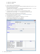


Table Of Contents
- HP Utility Meter User's Guide for version 8.15
- Table of Contents
- About This Document
- 1 Introduction
- 2 Installing and Configuring the Utility Meter Software
- 2.1 Overview
- 2.2 Skills Required
- 2.3 Before Going to the Customer Site
- 2.4 Configuring the HP-UX System Parameters
- 2.5 Obtaining and Installing the Utility Meter Software
- 2.6 Configuring the Utility Meter Parameters
- 2.7 URS XP Only – Installing the CV XP AE CLI Software
- 2.8 URS EVA Only – Installing the CV EVA SSSU Software
- 2.9 URS HP/Brocade SAN Switch Only – Installing the SMI-S Agent Software
- 2.10 URS Cisco SAN Switch Only – Enabling the CIM Server
- 2.11 Email Hostname Masquerading
- 2.12 Configuring PPU Partitions and URS Devices
- 2.13 Verifying the Utility Meter Operation
- 2.14 Completing the Utility Meter Installation and Configuration
- 2.15 Upgrading the Utility Meter Software to Version 8.15
- 3 Performing Utility Meter Tasks
- 4 Verifying Utility Meter Operation
- 4.1 Verifying the Utility Meter Hardware is Operational
- 4.2 Verifying the Utility Meter Software is Operational
- 4.3 Verifying the CIM Server Software Is Operational
- 4.4 Verifying Connectivity from the Utility Meter to HP
- 4.5 Verifying the Data Acquisition Server is Running
- 4.6 Verifying the Utility Meter Data Transport Method
- 4.7 Verifying a PPU Partition
- 4.8 Verifying a Storage Device
- 4.8.1 Verifying a Device is Configured in the Utility Meter
- 4.8.2 Verifying a Device is Connected to the Utility Meter
- 4.8.3 Verifying the Connection from the Utility Meter to HP
- 4.8.4 XP Only – Verifying the Correct Version of CV XP AE CLI is Installed
- 4.8.5 EVA Only – Verifying the Correct Version of CV EVA SSSU is Installed
- 4.9 Verifying a SAN Device
- 5 Troubleshooting the Utility Meter
- A Site Preparation Form for Pay Per Use
- B Site Preparation Form for Utility Ready Storage
- C Data Fields Sent from the Utility Meter to HP
- Glossary
- Index

4. In the Add Device dialog box's Device Type drop-down list, select the SAN Switch – Cisco
item.
5. In the Add Device dialog box, enter values into the following fields:
• IP – Enter the IP address or hostname of the SAN switch.
• Info – (Optional) Enter a description for the SAN switch.
• Login – Enter the username of the SAN switch.
• Password – Enter the password of the SAN switch.
• Require server certificate – Select Yes (default) if you want to require a server certificate
when the switch is accessed or No if you don't want to require a server certificate. See
Section 3.5.1.4: “Add a Cisco SAN Switch” for information about adding the certificate to the
sandevices.pem file. Note that this should be done before the SAN switch is added to the Utility
Meter.
6. Click the Add Device button. An information message appears. If no errors occur, such as duplicate
device ID, the SAN switch is added and listed in the Status field. If an error occurs, the Status field
displays the error message.
7. To add another SAN switch, repeat this procedure starting with Step 5; otherwise, click the Done button
to close the Add Device dialog box.
3.5.1.5 Add an HP/Brocade SAN Switch
This task allows you to add one or more HP/Brocade SAN switches to the Utility Meter. The configured SAN
switches are visible in the Utility Meter GUI's Managed Devices Tree in the Managed Devices (left) pane.
IMPORTANT: If you are going to require a server certificate for the SAN switch, you need to update the
sandevices.pem file before you add the SAN switch.
When a SAN switch is added to the Utility Meter you have the option of requiring a server certificate when
the switch is accessed. The certificate is different for each switch that you want to connect to. For each
metered switch, you need to copy the certificate file from the remote switch to the server the meter is running
on and then add it into /var/opt/meter/sandevices.pem, which is used to store the certificates for
every SAN switch for which you want to require a certificate. To copy the certificate from the metered switch
and add it to sandevices.pem, use the following procedure:
1. Create a file called ssl.conf. The distinguished_name should be unique for each switch. Here
is the sample ssl.conf:
[req]
distinguished_name = server.domain.com
prompt = no
[server.domain.com]
CN = server.domain.com
emailAddress = user@domain.com
2. Generate a private key and certificate using the following openssl command:
# openssl req –x 509 –days 365 –newkey ras:2048 –nodes –config ./ssl.conf
–keyout ./key.pem –out ./cert.pem
3. Concatenate the private key and certificate into a single file:
# cat key.pem cert.pem > cimserver1.pem
4. Login into switch and copy the certificate from the source to the switch:
# copy source/cimserver1.pem switch:cimserver1.pem
5. Enable the certificate in cimserver configuration:
# config t
# cimserver certificate switch:cimserver1.pem
3.5 Utility Meter Devices Tasks 59