
HP P4000 G2 10 GbE SFP+ Installation Instructions (B7E22-96001, December 2013)
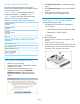
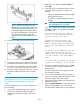

4. Locate the PCI cage.
a. Loosen the two thumb screws and the rear
conventional screw
b. Lift the assembly straight up.
NOTE: The PCI cage is the same for both
the P4300 G2 and the P4500 G2.
However, the P4500 G2 PCI cage has a
DVD drive mounted to the top.
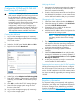
5. Remove the slot cover from the PCI cage.
6. Install the 10 GbE board into the open slot in the
PCI cage.
Make sure the board is fully seated in the slot,
then tighten the anchor screw.
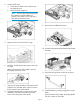
7. Align the PCI cage assembly to the system board
expansion slot, and then press it down to ensure
full connection to the system board.
8. Tighten the thumbscrews to secure the PCI cage
assembly to the system board and secure the
screw on the rear panel of the chassis.
9. Remove the air baffle from the unit.
10. Locate the appropriate empty RAM slot and install
the RAM.
11. Open the locking latches on this slot as shown.
12. Install the RAM by pushing straight down on the
RAM.
When the RAM is fully seated, the locking latches
will lock in place on each side.
Page 4