
FW V06.XX/HAFM SW V08.02.00 HP StorageWorks SAN High Availability Planning Guide (AA-RS2DD-TE, July 2004)


Table Of Contents
- SAN HA Planning Guide
- Contents
- About this Guide
- Introduction to HP Fibre Channel Products
- Product Management
- Planning Considerations for Fibre Channel Topologies
- Fibre Channel Topologies
- Planning for Point-to-Point Connectivity
- Characteristics of Arbitrated Loop Operation
- Planning for Private Arbitrated Loop Connectivity
- Planning for Fabric-Attached Loop Connectivity
- Planning for Multi-Switch Fabric Support
- Fabric Topologies
- Planning a Fibre Channel Fabric Topology
- Fabric Topology Design Considerations
- FICON Cascading
- Physical Planning Considerations
- Port Connectivity and Fiber-Optic Cabling
- HAFM Appliance, LAN, and Remote Access Support
- Inband Management Access (Optional)
- Security Provisions
- Optional Features
- Configuration Planning Tasks
- Task 1: Prepare a Site Plan
- Task 2: Plan Fibre Channel Cable Routing
- Task 3: Consider Interoperability with Fabric Elements and End Devices
- Task 4: Plan Console Management Support
- Task 5: Plan Ethernet Access
- Task 6: Plan Network Addresses
- Task 7: Plan SNMP Support (Optional)
- Task 8: Plan E-Mail Notification (Optional)
- Task 9: Establish Product and HAFM Appliance Security Measures
- Task 10: Plan Phone Connections
- Task 11: Diagram the Planned Configuration
- Task 12: Assign Port Names and Nicknames
- Task 13: Complete the Planning Worksheet
- Task 14: Plan AC Power
- Task 15: Plan a Multi-Switch Fabric (Optional)
- Task 16: Plan Zone Sets for Multiple Products (Optional)
- Index
Planning Considerations for Fibre Channel Topologies
103SAN High Availability Planning Guide
When designing a core-to-edge fabric, servers and storage devices that support
such bandwidth-intensive applications should be attached to core directors as Tier
1 devices. As a best practices policy (assuming 1.0625 Gbps ISLs), devices that
generate a sustained output of 35 MBps or higher are candidates for Tier 1
connectivity. IBM FICON devices also must use Tier 1 connectivity. For
additional information, refer to “FCP and FICON in a Single Fabric” on page 110.
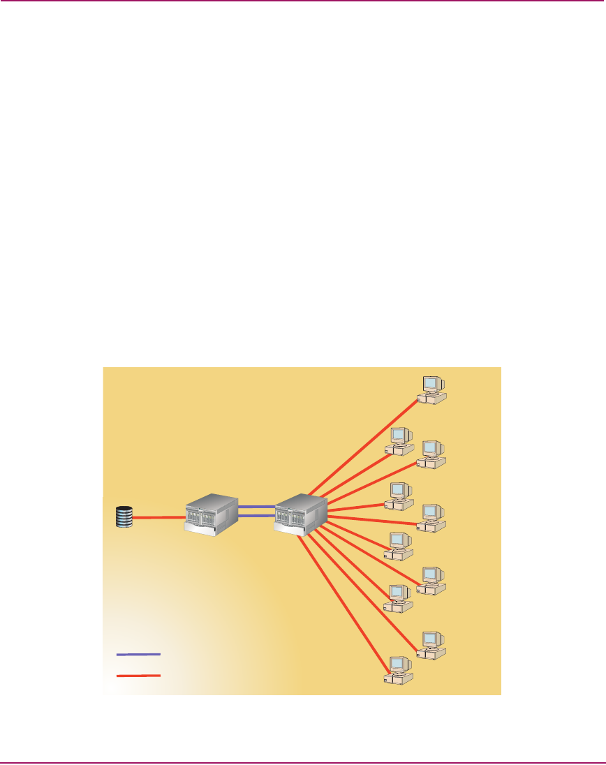
Device Fan-Out Ratio
The output of most host devices is bursty in nature; most devices do not sustain
full-bandwidth output, and it is uncommon for the output of multiple devices to
peak simultaneously. These variations are why multiple hosts can be serviced by a
single storage port. This device sharing leads to the concept of fan-out ratio.
Device fan-out ratio is defined as the storage or array port IOPS divided by the
attached host IOPS, rounded down to the nearest whole number. A more
simplistic definition for device fan out is the ratio of host ports to a single storage
port. Fan-out ratios are typically device dependent. In general, the maximum
device fan-out ratio supported is 12 to 1. Figure 43 illustrates a fan-out ratio of 10
to 1.
Figure 43: Device fan-out ratio
T
M
T
M
Interswitch Link
Fabric Connection
1,000 IOPS
1,000 IOPS
1,000 IOPS
1,000 IOPS
1,000 IOPS
1,000 IOPS
10,000 IOPS
1,000 IOPS
1,000 IOPS
1,000 IOPS
1,000 IOPS
Device Fan-Out Ratio: 10 to 1