HP Integrity BL860c i4, BL870c i4 & BL890c i4 Server Blade Installation Guide Abstract This document contains specific information that is intended for users of this HP product.
© Copyright 2012, 2013 Hewlett-Packard Development Company, L.P. The information contained herein is subject to change without notice. The only warranties for HP products and services are set forth in the express warranty statements accompanying such products and services. Nothing herein should be construed as constituting an additional warranty. HP shall not be liable for technical or editorial errors or omissions contained herein.
Contents 1 Installing the server blade into the enclosure..................................................4 Installation sequence and checklist..............................................................................................4 Installing and powering on the server blade.................................................................................4 Preparing the enclosure........................................................................................................
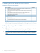
1 Installing the server blade into the enclosure Installation sequence and checklist Step Description 1 Perform site preparation (see the HP Integrity BL860c i4, BL870c i4 & BL890c i4 Server Blade User Service Guide for more information). 2 Unpack and inspect the server shipping container and then inventory the contents using the packing slip. 3 Install additional components shipped with the server. For these procedures, see the documentation that with the component or the user service guide.
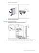
1. Remove the device bay blank. 2. Remove the three adjacent blanks. Removing a c7000 device bay divider 1. Slide the device bay shelf locking tab to the left to open it. 2. Push the device bay shelf back until it stops, lift the right side slightly to disengage the two tabs from the divider wall, and then rotate the right edge downward (clockwise).
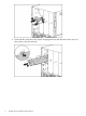
3. 6 Lift the left side of the device bay shelf to disengage the three tabs from the divider wall, and then remove it from the enclosure.
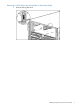
Removing a c3000 device bay mini-divider or device bay divider 1. Slide the locking tab down.
2. Remove the mini-divider or divider: • c3000 mini-divider: Push the divider toward the back of the enclosure until the divider drops out of the enclosure. • a. b. c. d. c3000 divider Push the divider toward the back of the enclosure until it stops. Slide the divider to the left to disengage the tabs from the wall. Rotate the divider clockwise. Remove the divider from the enclosure.
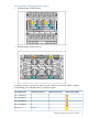
Interconnect bay numbering and device mapping • HP BladeSystem c7000 Enclosure • HP BladeSystem c3000 Enclosure To support network connections for specific signals, install an interconnect module in the bay corresponding to the embedded NIC or mezzanine signals.
Server blade signal c7000 interconnect bay c3000 interconnect bay Mezzanine 2 5 and 6 3 and 4 7 and 8 3 and 4 5 and 6 3 and 4 7 and 8 3 and 4 Mezzanine 3 Interconnect bay labels For detailed port mapping information, see the HP BladeSystem enclosure installation poster or the HP BladeSystem enclosure setup and installation guide for your product on the HP website (http://www.hp.com/go/bladesystem/documentation).
3. Install the server blade. The server blade should come up to standby power. The server blade is at standby power if the blade power LED is amber. Server blade power states The server blade has three power states: standby power, full power, and off. Install the server blade into the enclosure to achieve the standby power state. Server blades are set to power on to standby power when installed in a server blade enclosure. Verify the power state by viewing the LEDs on the front panel, and using Table 1.
Powering on the server blade Use one of the following methods to power on the server blade: NOTE: To power on blades in a conjoined configuration, only power on the Monarch blade. See “ Blade Link bay location rules” for rules on the definition of the Monarch blade. • Use a virtual power button selection through iLO 3. • Press and release the Monarch power button. When the server blade goes from the standby mode to the full power mode, the blade power LED changes from amber to green.
NOTE: Before installing the Blade Link for BL870c i4 or BL890c i4, make sure the following statements are true: • All blades have the same CPU SKUs • All blades have the same hardware revision (only use BL860c i4, BL870c i4, or BL890c i4 Server Blades) • All blades have CPU0 installed • All blades have the same firmware revision set • All blades follow the memory loading rules for your configuration, see the HP Integrity BL860c i4, BL870c i4 & BL890c i4 Server Blade User Service Guide • The enclo
Number of conjoined blades Class BL2E BL4 1 Supported enclosures Partner blade Blade location rules support? c3000 Bays 1&2, 3&4 with Monarch blade in odd bay Partner blade half-height bay number / Server blade full-height bay number 2 (BL870c i4) c7000 only Bays 2&3, 4&5 or 6&7 with Monarch blade in even bay using full-height numbering Yes Bottom half-height bay 9 paired with full-height bays 2&3, bottom half-height bay 11 paired with full-height bays 4&5, bottom half-height bay 13 paired with
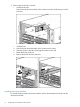
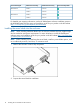
7. 8. 9. Push in the blue release latch on the handle to release the handle. Pull the handle all the way out Align the guide pins on the back of the Blade Link to the holes on the front of the server blades. As you insert the pins into the holes, ensure the face on the Blade Link is evenly aligned parallel to the face of the server blades. 10. Press firmly on the left and right sides of the Blade Link face until the handle naturally starts to close.
15. Still in the iLO 3 Command Menu, power on the Monarch blade with the PC -on -nc command. Powering on the Monarch blade will power the entire conjoined system on. 16. Boot the Monarch blade. Booting the Monarch blade boots the entire conjoined system. Using iLO 3 The iLO 3 subsystem is a standard component of selected server blades that monitors blade health and provides remote server manageability.
NOTE: 4. If no option is selected, normal boot will proceed after ten seconds. Depending on how the server blade was configured from the factory, and if the OS is installed at the time of purchase, you are taken to: • UEFI shell prompt • OS login prompt If the server blade has a factory-installed OS, you can interrupt the boot process to configure your specific UEFI parameters. If you are at the UEFI shell prompt, go to “UEFI Front Page” (page 17).
To configure specific devices, press D or d to launch the Device Manager. This is an advanced feature and should only be performed when directed. To perform maintenance on the system such as adding, deleting, or reordering boot options, press M or m to launch the Boot Maintenance Manager.
To perform more advanced operations, press S or s to launch the UEFI Shell. To view the iLO 3 LAN configuration, press I or i to launch the iLO 3 Setup Tool. Saving UEFI configuration settings There are other UEFI settings you can configure at this time. For more UEFI configuration options, see the HP Integrity BL860c i4, BL870c i4 & BL890c i4 Server Blade User Service Guide.
Installing the latest firmware using HP Smart Update Manager The HP Smart Update Manager utility enables you to deploy firmware components from either an easy-to-use interface or a command line. It has an integrated hardware discovery engine that discovers the installed hardware and the current versions of firmware in use on target servers. This prevents extraneous network traffic by only sending the required components to the target.
2 Support and other resources Contacting HP Before you contact HP Be sure to have the following information available before you call contact HP: • Technical support registration number (if applicable) • Product serial number • Product model name and number • Product identification number • Applicable error message • Add-on boards or hardware • Third-party hardware or software • Operating system type and revision level HP contact information For the name of the nearest HP authorized reseller
HP Insight Remote Support Software HP strongly recommends that you install HP Insight Remote Support software to complete the installation or upgrade of your product and to enable improved delivery of your HP Warranty, HP Care Pack Service or HP contractual support agreement.
CAUTION A caution calls attention to important information that if not understood or followed will result in data loss, data corruption, or damage to hardware or software. IMPORTANT This alert provides essential information to explain a concept or to complete a task NOTE A note contains additional information to emphasize or supplement important points of the main text.
Standard terms, abbreviations, and acronyms A ASIC Application-specific integrated circuit Auxiliary Any blade in a conjoined server other than the lowest-numbered blade B BBRAM Battery-backed RAM BBWC Battery Backed Write Cache BCH Boot console handler C CE Customer engineer CEC Core electronics complex CMC Corrected machine check CPE Corrected platform errors CRU Customer replaceable unit CSR Control status registers D DDNS Dynamic domain name system DHCP Dynamic host configuratio
L LDAP Lightweight directory access protocol LVM Logical volume manager M Monarch Designates a single-blade server, or lowest-numbered blade in a conjoined server MP Management processor MPS Maximum payload size N NIC Network interface card NVRAM Non-Volatile RAM O OA Onboard Administrator ORCA Option Rom Configuration for Arrays P PA-RISC Precision Architecture, Reduced Instruction Set Computing PCA Printed circuit assembly PCI Peripheral component interface PCI-X Peripheral compon
TUI Text user interface U UART Universal asynchronous receiver-transmitter UEFI Unified Extensible Firmware Interface, replaces EFI.
A Regulatory information For important safety, environmental, and regulatory information, see Safety and Compliance Information for Server, Storage, Power, Networking, and Rack Products, available at http:// www.hp.com/support/Safety-Compliance-EnterpriseProducts.
Index B U Blade Link installing, 12 c-Class enclosure see enclosure UEFI accessing from iLO 3 MP, 16 Front Page, 17 saving configuration settings, 19 Ukraine RoHS material content declaration, 27 E V enclosure interconnect mapping, 9 interconnect modules, 8 LAN ports, 8 virtual power button, 12 C F firmware updates, 20 H HP Smart Update Manager, 20 HP-UX Ignite, 19 HPSUM see HP Smart Update Manager I iLO 3 MP accessing UEFI from, 16 installing Blade Link, 12 server blade into enclosure, 4, 10 N