HP Neoview Owner's Manual HP Part Number: 541592-007 Published: August 2007
© Copyright 2007 Hewlett-Packard Development Company, L.P. Legal Notice Confidential computer software. Valid license from HP required for possession, use or copying. Consistent with FAR 12.211 and 12.212, Commercial Computer Software, Computer Software Documentation, and Technical Data for Commercial Items are licensed to the U.S. Government under vendor’s standard commercial license. The information contained herein is subject to change without notice.
Table of Contents About This Document.........................................................................................................7 Intended Audience.................................................................................................................................7 New and Changed Information in This Edition.....................................................................................7 Document Organization.....................................................................
Receiving and Unpacking Space...........................................................................................................21 Operational Space.................................................................................................................................21 5 Preparing Your LAN Infrastructure for the Neoview Platform..................................23 Overview......................................................................................................................
Safety and Compliance..................................................................................................49 Index.................................................................................................................................
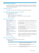
About This Document This manual describes the HP Neoview Data Warehousing Platform for Business Intelligence. It includes information for hardware operations and site planning as well as physical, electrical, and environmental specifications. Intended Audience This manual is written for Neoview platform customers and their site planners.
• • Neoview Management Dashboard Client Guide for Database Administrators Information on using the Dashboard Client, including how to install the Client, start and configure the Client Server Gateway (CSG), use the Client windows and property sheets, interpret entity screen information, and use Command and Control to manage queries from the Client. Neoview Owner’s Manual Site-planning information and basic hardware information.
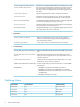
HP Encourages Your Comments HP encourages your comments concerning this document. We are committed to providing documentation that meets your needs. Send any errors found, suggestions for improvement, or compliments to: pubs.comments@hp.com Include the document title, part number, and any comment, error found, or suggestion for improvement you have concerning this document.
1 Introduction to the Neoview Platform Overview The HP Neoview Data Warehousing Platform for Business Intelligence leverages the reliability and clustering technology of HP servers and the complex query technology of the HP database to provide parallelism, high scalability, and high-volume storage. The platform has predefined packaged configurations and services that are easy to install, tune, and manage. CAUTION: This product is prepackaged and has been validated for Neoview platform use only.
• • • 12 HP performed server startup and shutdown HP multimedia training CD HP upgraded software as needed for updates Introduction to the Neoview Platform
2 Neoview Platform Operations General Safety Guidelines WARNING! Do not touch areas marked HAZARDOUS, even with the power off. These areas contain high-voltage power, and touching them could result in serious injury. CAUTION: Do not perform any procedures on the Neoview platform except the Emergency Power Off procedure described in this section. If you have any questions or concerns, contact your HP support representative. Do not power off the Neoview platform unless an emergency occurs.
Customer Responsibilities for Powerfail Recovery • • • • • • Ensure power is available to all Neoview platform segments Confirm the Neoview system consoles have power and the consoles have rebooted Confirm your network is fully operational Confirm the Neoview DL580 Loaders have power During an extended power outage, contact the Global Mission Critical Solution Center (GMCSC) to perform an orderly shutdown of the Neoview platform before the site-wide uninterruptible power supplies (UPS's) drain power and t
3 Neoview Platform Configurations There are seven types of Neoview platform configurations: • • • • • • • 16-node configuration (2 cabinets, 2 disk pairs per node) 32-node configuration (3 cabinets, 2 disk pairs per node) 48-node configuration (5 cabinets, 2 disk pairs per node) 64-node configuration (6 cabinets, 2 disk pairs per node) 96-node configuration (9 cabinets, 2 disk pairs per node) 128-node configuration (12 cabinets, 2 disk pairs per node) 256-node configuration (23 cabinets, 2 disk pairs per n
48-Node Configuration 64-Node Configuration 96-Node Configuration 16 Neoview Platform Configurations
128-Node Configuration 256-Node Configuration 128-Node Configuration 17
4 Neoview Platform Installation Site Guidelines Neoview Platform Power and I/O Cable Entry You can order the segment and combination cabinets with the PDU junction boxes installed: • • Top rear: Power cables are routed from above the cabinet. Bottom rear: Power cables are routed from below the cabinet (HP recommended). I/O cables can enter the Neoview platform segment and combination cabinets from the bottom rear, top rear, or rear sides of the cabinet.
Grounding Systems The site building must provide a power distribution safety ground/protective earth for each AC service entrance to all Neoview platforms and associated components. This safety grounding system must comply with local codes and any other applicable regulations for the installation locale. For proper grounding/protective earth connection, consult your HP site preparation specialist or power engineer. Power Consumption For information, see “Cabinet Power Loads” (page 29).
electronic components on printed circuit boards inhibiting cooling airflow and causing premature failure from excess heat, humidity, or both. Metallically conductive particles can short circuit electronic components. Tape drives and some other mechanical devices can experience failures resulting from airborne abrasive particles. For recommendations to keep the site as free of dust and pollution as possible, consult with your HVAC engineer or your HP site preparation specialist.
• • 22 Power-conditioning equipment Storage area or cabinets for supplies, media, and spare parts Neoview Platform Installation Site Guidelines
5 Preparing Your LAN Infrastructure for the Neoview Platform This section provides guidelines for preparing your LAN infrastructure for the Neoview platform. Overview A pair of HP ProCurve 2848 switches tie together both the internal and external LAN networks. The segments attach to the dedicated service LAN, your enterprise query LAN, the data load and extract LAN, and the HP Instant Support Enterprise Edition (ISEE) solution LAN.
You must use router-based connectivity for the Neoview platform. If you use a pair of routers, trunk them together or use Hot Standby Router Protocol (HSRP). This illustration shows connectivity to a customer environment by means of routers. Neoview S egment #2 Neoview S egment #1 Neoview S egment # 3 Neoview S egment #4 Neoview S egment #5 Neoview S egment #6 Neoview S egment # 7 Neoview S egment #8 s2 .5 s3 .5 s2 .5 s3 .5 s2 .5 s3 .5 s2 .5 s3 .5 s2 .5 s3.5 s2.5 s3 .5 s2 .5 s3 .5 s2.
A Installation Specifications for the Neoview Platform Neoview Platform Footprint The Neoview platform layout consists of segment and combination cabinets. The total number of cabinets depends on your specific configuration. This illustration shows the footprint for one cabinet. For illustrations of the Neoview platform configuration types, see Chapter 3 (page 15). For information about service clearances for the Neoview platform, see “Service Clearances” (page 25). Service Clearances Aisles: 6 feet (182.
Physical Specifications Item Height Width Depth in. cm. in. cm. in. cm. Cabinet 78.7 199.9 24.0 60.96 46.0 116.84 Rack 78.5 199.9 23.62 60.0 40.0 101.9 Shipping (palletized) 86.22 219.0 32.0 81.28 54.0 137.
Supported PDUs and Power Offerings The Neoview platform PDUs are available in four static strapping configurations that are factory-installed in a segment or combination cabinet.
North America and Japan 200 to 240 V AC Input, Single Phase, 40A RMS Modular Cabinet • • • • • • • EIA standard 19-inch rack with 42U of rack space Geography: North American and Japan Recommended for most configurations Two power distribution units (PDU), zero-U rack design PDU input characteristics — 200 to 240 V ac, single phase, 40A RMS, 3-wire — 50/60Hz — Non-NEMA Locking CS8265C, 50A input plug — 6.
Grounding A safety ground/protective earth conductor is required for each AC service entrance to the segment and combination cabinets. This ground must comply with local codes and any other applicable regulations.
Enclosure AC Input Enclosures (such as processor switch, IOAM, and so forth) require: Specification Value Nominal input voltage 1 200/208/220/230/240 V ac RMS Voltage range 180-254 V ac Nominal line frequency 50 or 60 Hz Frequency ranges 47-53 Hz or 57-63 Hz Number of phases 1 1 Voltage range for the maintenance switch is 200-240 V ac. Each PDU is factory wired to distribute the phases to its receptacles.
Environmental Specifications Cabinet Type Unit Heat (single PDU powered - BTU per hour) Unit Heat (both PDUs powered - BTU per hour) Segment 15880 19060 16-node configuration 28249 32978 32-node configuration 46759 55218 48-node configuration 65270 77458 64-node configuration 83781 99698 96-node configuration 120802 144178 128-node configuration 164941 196776 256-node configuration 320539 383210 Combination: Operating Temperature, Humidity, and Altitude Specification Operating R
Nonoperating Temperature, Humidity, and Altitude • • • Temperature: — Up to 72-hour storage: - 40× to 150× F (-40× to 66× C) — Up to 6-month storage: -20× to 131× F (-29× to 55× C) — Reasonable rate of change with noncondensing relative humidity during the transition from warm to cold Relative humidity: 10 percent to 80 percent, noncondensing Altitude: 0 to 40,000 feet (0 to 12,192 meters) Cooling Airflow Direction Each enclosure includes its own forced-air cooling fans or blowers.
B Site Preparation Walk-Through This appendix provides a site appraisal form for HP account teams and professional service delivery consultants.
Overview HP support engineers and Professional Service delivery consultants use this questionnaire to collect data and identify areas of concern that can affect installation, supportability, or operational reliability of new or relocated equipment within a data center. The obtained information can also be included with other HP service offerings to assist customers in improving their existing data center or when building a new facility intended for HP systems.
Sections • • • • • • • • “Computer Room” (page 36) “Power and Lighting” (page 38) “Safety” (page 40) “Air Conditioning” (page 41) “EMI and RFI” (page 42) “Storage” (page 42) “Building Access, Security, and Equipment Delivery” (page 43) “Communication” (page 46) Sections 35
Computer Room 36 Site Preparation Walk-Through
Computer Room 37
Power and Lighting 38 Site Preparation Walk-Through
Power and Lighting 39
Safety 40 Site Preparation Walk-Through
Air Conditioning Air Conditioning 41
EMI and RFI Storage 42 Site Preparation Walk-Through
Building Access, Security, and Equipment Delivery Building Access, Security, and Equipment Delivery 43
Site Preparation Walk-Through
Building Access, Security, and Equipment Delivery 45
Communication Floor Plan This is the proposed floor plan to use for sketching. Use drawing software (for example, Visio) to supply a finished copy. If a floor plan is not available from the customer, draw in the proposed location of the equipment. Include all cabinets, walls, doors, and air conditioners. 1 square = 600 mm or 23.62 inches.
Floor Plan 47
Safety and Compliance This section contains three types of required safety and compliance statements: • • • Regulatory compliance Waste Electrical and Electronic Equipment (WEEE) Safety Regulatory Compliance Statements The following regulatory compliance statements apply to the products documented by this manual. FCC Compliance This equipment has been tested and found to comply with the limits for a Class A digital device, pursuant to part 15 of the FCC Rules.
Taiwan (BSMI) Compliance Japan (VCCI) Compliance This is a Class A product based on the standard or the Voluntary Control Council for Interference by Information Technology Equipment (VCCI). If this equipment is used in a domestic environment, radio disturbance may occur, in which case the user may be required to take corrective actions.
Product in accordance with US FDA regulations and the IEC 60825-1. The product does not emit hazardous laser radiation. WARNING: Use the controls or adjustments or performance of procedures other than those specified herein or in the laser product’s installation guide may result in hazardous radiation exposure. To reduce the risk of exposure to hazardous radiation: • Do not try to open the module enclosure. There are no user-serviceable components inside.
“HIGH LEAKAGE CURRENT, EARTH CONNECTION ESSENTIAL BEFORE CONNECTING SUPPLY” “HOHER ABLEITSTROM. VOR INBETRIEBNAHME UNBEDINGT ERDUNGSVERBINDUNG HERSTELLEN” “COURANT DE FUITE E’LEVE’. RACCORDEMENT A LA TERRE INDISPENSABLE AVANT LE RACCORDEMENT AU RESEAU” FUSE REPLACEMENT CAUTION – For continued protection against risk of fire, replace fuses only with fuses of the same type and the same rating. Disconnect power before changing fuses.
Index A M AC power 200 to 240 V ac single phase 32A RMS, 28 200 to 240 V ac single phase 40A RMS, 28 208 V ac 3-phase delta 24A RMS, 27 380 to 415 V ac 3-phase Wye 16A RMS, 28 enclosure input specifications, 30 unstrapped PDU, 27 Access readiness inspection, 43 Air conditioning readiness inspection, 41 Air filters, 20 Appraisal, site readiness;Installation, readiness inspection, 33 Metallic particulate contamination, 21 C R Cabinet 200 to 240 V ac input, Single phase, 32A RMS, 28 200 to 240 V ac input