
HP Surestore NAS 8000 High Availability Solution Integration Manual

34 Installation Guide
Connecting VA 7100 Arrays
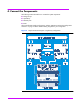
To connect a single VA 7100 array (see “Sample Connection Diagram - Single Array
Configuration” on page 31):
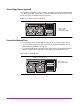
1. Connect the array to node 1:
— Remove the protective cover from the FC Port 1 connector on the array.
— Verify that a GBIC is connected to host FC Port 1 on the array, then plug one end of a
fiber optic cable into the GBIC.
— Plug the other end of the fiber optic cable into the mating optical connector on the Fibre
Channel HBA card in the NAS server designated as node 1.
2. Connect the array to node 2:
— Remove the protective cover from the FC Port 2 connector on the array.
— Verify that a GBIC is connected to host FC Port 2 on the array, then plug one end of a
fiber optic cable into the GBIC.
— Plug the other end of the fiber optic cable into the mating optical connector on the Fibre
Channel HBA card in the NAS server designated as node 2.
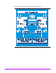
To connect one or two VA 7100 arrays with a FC switch (see “Sample Connection Diagram -
Dual Array Configuration” on page 32):
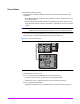
1. Connect the NAS servers to the FC switch:
— Each NAS server has two FC HBAs. On each NAS server, plug a fiber optic cable into
the optical connectors on each FC HBA.
— Plug the other end of each cable from NAS server 1 into the optical connectors on FC
switch 1.
— Plug the other end of each cable from NAS server 2 into the optical connectors on FC
switch 2.
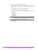
2. Connect the arrays to the FC switch:
— Remove the protective cover from the FC Port connectors on each array.
— Verify that a GBIC is connected to the FC Port connectors on each array, then plug one
end of a fiber optic cable into each GBIC.
— Plug one cable from array 1 into an optical connector on FC switch 1 and plug the
second cable into a connector of FC switch 2.
— Plug one cable from array 2 into an optical connector on FC switch 1 and plug the
second cable into a connector of FC switch 2.
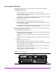
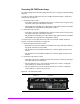
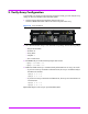
Figure 7 VA 7100 FC Ports
FC Port 1 FC Port 2