
R2511-HP MSR Router Series Voice Configuration Guide(V5)

253
[RouterC-voice-dial] entity 3000 pots
[RouterC-voice-dial-entity3000] line 1/0
[RouterC-voice-dial-entity3000] match-template 3000
Call transfer
Network requirements
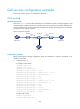
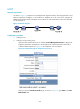
As shown in Figure 73, call transfer enables Telephone A to transfer Telephone B to Telephone C. After
the call transfer is completed, Telephone B and Telephone C are in a conversation.
The whole process is as follows:
1. Call Telephone B from Telephone A, so that Telephone B and Telephone A are in a conversation.
2. Perform a hookflash at Telephone A to put the call with Telephone B on hold.
3. Call Telephone C (3000) from Telephone A after hearing dial tones.
4. Hang up Telephone A.
5. Telephone B and Telephone C are in a conversation and call transfer is completed.
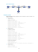
Figure 73 Network diagram
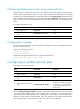
Configuration procedure
Before performing the following configuration, make sure that Router A, Router B and Router C are
routable to each other.
1. Configure Router A:
<RouterA> system-view
[RouterA] voice-setup
[RouterA-voice] dial-program
[RouterA-voice-dial] entity 2000 voip
[RouterA-voice-dial-entity2000] address sip ip 10.1.1.2
[RouterA-voice-dial-entity2000] match-template 2000
[RouterA-voice-dial-entity2000] quit
[RouterA-voice-dial] entity 3000 voip
[RouterA-voice-dial-entity3000] address sip ip 20.1.1.2
[RouterA-voice-dial-entity3000] match-template 3000
[RouterA-voice-dial-entity3000] quit
[RouterA-voice-dial] entity 1000 pots
[RouterA-voice-dial-entity1000] line 1/0
[RouterA-voice-dial-entity1000] match-template 1000
[RouterA-voice-dial-entity1000] return
1000
Eth1/1
10.1.1.1/24
3000
Router A
Eth1/1
20.1.1.2/24
2000
Eth1/2
10.1.1.2/24
Eth1/1
20.1.1.1/24
Router B Router C
Telephone B
Telephone C
Telephone A