HP StorageWorks 70 Modular Smart Array Enclosure maintenance and service guide This guide provides procedures and diagnostics needed for the maintenance and troubleshooting of the HP StorageWorks 70 Modular Smart Array Enclosure.
© Copyright 2007 Hewlett-Packard Development Company, L.P. The information contained herein is subject to change without notice. The only warranties for HP products and services are set forth in the express warranty statements accompanying such products and services. Nothing herein should be construed as constituting an additional warranty. HP shall not be liable for technical or editorial errors or omissions contained herein. Windows is a U.S. registered trademark of Microsoft Corporation.
Contents About this guide ........................................................................................................................... 6 Intended audience..................................................................................................................................... 6 Prerequisites ............................................................................................................................................. 6 Document conventions and symbols ...............
Installing the access panel .............................................................................................................. 27 Hard drive blank ..................................................................................................................................... 27 Removing the hard drive blank ........................................................................................................ 27 Installing the hard drive blank ..............................................
Riser board ............................................................................................................................................ 43 Before you begin........................................................................................................................... 43 Verifying component failure ............................................................................................................ 43 Removing the riser board.................................................
About this guide This maintenance and service guide provides information to help you: • Service the HP StorageWorks 70 Modular Smart Array Enclosure (MSA70) • Troubleshoot the MSA70 About this guide topics include: • Intended audience • Prerequisites • Document conventions and symbols • HP technical support • Subscription service • HP websites • Documentation feedback Intended audience This guide is intended for use by system administrators and technicians who are experienced with the foll
Italic text Text emphasis Monospace text • File and directory names • System output • Code • Commands, their arguments, and argument values Monospace, italic text • Code variables • Command variables Monospace, bold text Emphasized monospace text WARNING! Indicates that failure to follow directions could result in bodily harm or death. CAUTION: Indicates that failure to follow directions could result in damage to equipment or data.
Subscription service HP recommends that you register your product at the Subscriber’s Choice for Business website: http://www.hp.com/go/e-updates. After registering, you will receive e-mail notification of product enhancements, new driver versions, firmware updates, and other product resources. HP websites For additional information, see the following HP websites: • http://www.hp.com • http://www.hp.com/go/storage • http://www.hp.com/service_locator • http://www.hp.
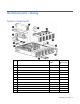
Illustrated parts catalog System components Item Description Spare part number Customer self repair (on page 19) 1 Hard drives — — a) 36-GB SAS, 10,000 rpm 376596-001 Mandatory1 b) 36-GB SAS, 15,000 rpm * 432332-001 Mandatory1 c) 72-GB SAS, 10,000 rpm * 447447-021 Mandatory1 d) 72-GB SAS, 15,000 rpm * 418373-001 Mandatory1 e) 146-GB SAS 10,000 rpm * 432320-001 Mandatory1 f) 60-GB SATA, 5,400 rpm * 405419-001 Mandatory1 g) 80-GB SATA, 5,400 rpm * 431907-00 Mandatory1 h) 160-GB S
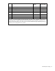
Item Description Spare part number Customer self repair (on page 19) 5 7-segment display board 399057-001 Optional2 6 Power supply 405914-001 Mandatory1 7 Riser board 399056-001 Optional2 8 Midplane 430148-001 Optional2 9 Backplane 430149-001 Optional2 10 Power on/off module 399055-001 Optional2 11 Front UID module 399053-001 Optional2 12 Plastic bezel N/A N/A *Not shown 1Mandatory—Parts for which customer self repair is mandatory.
Specifications This chapter provides the environmental and enclosure specifications, and supported cable lengths for the MSA70. Environmental specifications Specification Value Temperature range Operating* 10°C to 35°C (50°F to 95°F) Maximum rate of change is 10º C/hr (50º F/hr) Storage -30°C to 60°C (-22°F to 140°F) Maximum rate of change is 20º C/hr (68º F/hr) Relative humidity** Operating 10% to 90% relative humidity (Rh), 28º C (82.
Supported cables A 0.5-m (1.64-ft) SAS cable ships standard with the enclosure. HP recommends using the shortest cable possible, however, other supported cable lengths between SAS ports are 2 m (6.56 ft), 4 m (13.12 ft), and 6 m (19.69 ft). To acquire different lengths, contact the nearest authorized HP reseller.
Identifying components This chapter identifies the components of the MSA70 and identifies and describes the status LEDs of the system: • Front panel components • Front panel LEDs • Rear panel components • Rear panel LEDs and buttons • Hard drive bay numbers • Hard drive LEDs • Hard drive LED combinations Front panel components Item Description 1 Hard drive bays 2 Front unit ID (UID) module Identifying components 13
Front panel LEDs Item Description Status 1 Heartbeat LED Green = System activity 2 Fault LED Amber = Fault condition Off = No system activity Off = No fault condition 3 UID button/LED Blue = Identified Blue flashing = Active remote management Off = No active remote management Rear panel components Item Description 1 Power supply 1 Identifying components 14
Item Description 2 Fan 1 3 7-segment display board 4 SAS in connector 5 SAS out connector 6 I/O module 7 For future use 8 Fan 2 9 Power supply 2 Rear panel LEDs and buttons Item Description Status 1 I/O module LED Green = System activity Amber = Fault condition Off = No system activity 2 UID button/LED Blue = Identified Blue flashing = Active remote management Off = No active remote management 3 Heartbeat LED Green = System activity Off = No system activity 4 Fan LED Green =
Item Description Status 7 Power supply LED Green = Power turned on and power supply functioning properly Amber = Standby (auxiliary power present) Blinking amber = Power to this power supply not present Off = One or more of the following conditions exists: • A/C power unavailable • Power supply failed • Power supply exceeded current limit Hard drive bay numbers Hard drive LEDs Identifying components 16
Item Description 1 Fault/UID LED (amber/blue) 2 Online/activity LED (green) Hard drive LED combinations NOTE: Predictive failure alerts can occur only when the enclosure is connected to a Smart Array controller. Online/activity LED Fault/UID LED (green) (amber/blue) Interpretation On, off, or flashing Alternating amber and blue The drive has failed, or a predictive failure alert has been received for this drive; it also has been selected by a management application.
Diagnostic tools This chapter describes the diagnostic tools available for the MSA70. Integrated Management Log The Integrated Management Log (IML) records events and stores them in an easy-to-view form. The IML timestamps each event with 1-minute granularity.
Customer replaceable components This chapter includes the following information regarding the removal and replacement of MSA70 components: • Overview of removal and replacement procedures • Description of Customer Self Repair • Description of all warnings and precautions to consider when removing and replacing components of the MSA70 IMPORTANT: To reduce the risk of personal injury or damage to the equipment, observe all warnings and cautions throughout this chapter.
service providers or service partners) identifies that the repair can be accomplished by the use of a CSR part, HP will ship that part directly to you for replacement. There are two categories of CSR parts: • Mandatory—Parts for which customer self repair is mandatory. If you request HP to replace these parts, you will be charged for the travel and labor costs of this service. • Optional—Parts for which customer self repair is optional. These parts are also designed for customer self repair.
Recommended tools When replacing certain components, such as the power on/off module, the following tools may be necessary: • Torx T-10 and Torx T-15 screwdrivers • Phillips screwdriver Warnings and precautions Electrostatic discharge information To prevent damage to the system, be aware of the precautions you need to follow when setting up the system or handling parts. A discharge of static electricity from a finger or other conductor may damage system boards or other static-sensitive devices.
Equipment symbols These symbols may be located on equipment in areas where hazardous conditions may exist. WARNING! Any enclosed surface or area of the equipment marked with these symbols indicates the presence of electrical shock hazards. Enclosed area contains no operator serviceable parts. To reduce the risk of injury from electrical shock hazards, do not open this enclosure. WARNING! Any RJ-45 receptacle marked with these symbols indicates a network interface connection.
WARNING! Verify that the AC power supply branch circuit that provides power to the rack is not overloaded. Overloading AC power to the rack power supply circuit increases the risk of personal injury, fire, or damage to the equipment. The total rack load should not exceed 80 percent of the branch circuit rating. Consult the electrical authority having jurisdiction over your facility wiring and installation requirements.
WARNING! To reduce the risk of personal injury or damage to the equipment, the installation of non-hot-pluggable components should be performed only by individuals who are qualified in servicing computer equipment, knowledgeable about the procedures and precautions, and trained to deal with products capable of producing hazardous energy levels. CAUTION: Before replacing a hot-pluggable component, ensure that steps have been taken to prevent loss of data.
Removal and replacement procedures This chapter describes how to power up and power down the MSA70, and how to remove and replace the following MSA70 components: • Access panel • Hard drive blank • Hot-plug SAS or SATA hard drive • Hot-plug power supply • Hot-plug fan • I/O module • Front UID module • Power on/off module • Power UID module • 7-segment display board • Riser board • Midplane • Backplane Powering up and powering down CAUTION: Be sure that the server to which the MSA70
1. Complete server hardware installation and cabling. See the server documentation. 2. Connect the SAS cables and power cords to the enclosure. 3. Press and hold the Power On/Standby button on the enclosure. Wait and observe the system power LED and fan modules. When the enclosure powers up, the system power LED illuminates solid green and the fans spin to a high speed, and then spin down to a low speed. 4. Power up the servers. See the server documentation.
WARNING! To reduce the risk of personal injury from hot surfaces, allow the drives and the internal system components to cool before touching them. CAUTION: To prevent damage to electrical components, properly ground the enclosure before beginning any installation procedure. Improper grounding can cause ESD. Installing the access panel To install the access panel, reverse the removal procedure: 1. Slide the access panel into place on the chassis. 2.
Hot-plug hard drive Before you begin CAUTION: • Before removing the failed component, make sure that you have the replacement part available. Removing a component impacts the airflow and cooling ability of the device. • Do not remove more than one component or blank from the enclosure at a time. Doing so impacts the airflow and cooling ability of the device. To avoid possible overheating, insert the new or replacement component as quickly as possible.
Online/activity LED Fault/UID LED (green) (amber/blue) Interpretation Off The drive is offline, a spare, or not configured as part of an array. Off You can replace hard drives without powering down the system. However, before replacing a degraded drive: • Open HP SIM and inspect the Error Counter window for each physical drive in the same array to confirm that no other drives have any errors.
2. Press the latch and slide it to the right to disengage the lever (1), and then open the lever (2). 3. Pull the hard drive out of the bay. Installing the hard drive To install the hard drive, reverse the removal procedure: 1. Slide the drive into the bay until it clicks, locking the drive into place. 2. Close the lever, making sure that it is flush with the front of the drive.
• Parts can be damaged by electrostatic discharge. Use proper anti-static protection.
Hot-plug fan Before you begin CAUTION: • Before removing the failed component, make sure that you have the replacement part available. Removing a component impacts the airflow and cooling ability of the device. • Do not remove more than one component or blank from the enclosure at a time. Doing so impacts the airflow and cooling ability of the device. To avoid possible overheating, insert the new or replacement component as quickly as possible.
Verifying component replacement After replacing the fan, check the fan status LED. I/O module Before you begin CAUTION: • Before removing the failed component, make sure that you have the replacement part available. Removing a component impacts the airflow and cooling ability of the device. • Do not remove more than one component or blank from the enclosure at a time. Doing so impacts the airflow and cooling ability of the device.
3. Squeeze the lever (1) and pull it down (2). 4. Slide the I/O module out of the chassis (3). Installing the I/O module To install the I/O module: 1. Squeeze the lever and pull it down. 2. Slide the I/O module into the chassis until it clicks into place. 3. Connect SAS cables to the module. 4. Power up the enclosure. Verifying component replacement After replacing the I/O module, check the I/O module status LED.
Blue = Identified Blue flashing = Active remote management Off = No active remote management • Check the host log for errors. Removing the front UID module 1. Power down the enclosure: a. Power down any attached servers. See the server documentation. b. Press the Power On/Standby button on the enclosure. c. Wait for the system power LED to go from green to amber. d. Disconnect the power cords. 2. Remove the plastic bezel (1). 3. Remove the T-10 screw to release the module from the chassis (2). 4.
Power on/off module Before you begin CAUTION: • Before removing the failed component, make sure that you have the replacement part available. Removing a component impacts the airflow and cooling ability of the device. • Do not remove more than one component or blank from the enclosure at a time. Doing so impacts the airflow and cooling ability of the device. To avoid possible overheating, insert the new or replacement component as quickly as possible.
a. Loosen the front panel thumbscrews that secure the enclosure faceplate to the front of the rack. b. Disconnect the cabling and extend or remove the enclosure from the rack. 3. Remove the access panel: c. Lift the access panel latch (1). d. Slide the access panel to the rear (2). 4. Remove the front UID module: a. Remove the plastic bezel (1). b. Remove the T-10 screw to release the module from the chassis (2). c. Remove the module (3). 5. Remove the power supply: a.
6. Disconnect the cable from the power on/off module (1). 7. Loosen the thumbscrew on the module (2). 8. Slide the module back to remove it from the guide, and then lift it out of the chassis (3). Installing the power on/off module To install the power on/off module, reverse the removal procedure: 1. Slide the module into the chassis using the guide and tighten the thumbscrew. 2. Connect the cable to the module. 3. Install the power supply and the front UID module. 4.
Power UID module Before you begin CAUTION: • Before removing the failed component, make sure that you have the replacement part available. Removing a component impacts the airflow and cooling ability of the device. • Do not remove more than one component or blank from the enclosure at a time. Doing so impacts the airflow and cooling ability of the device. To avoid possible overheating, insert the new or replacement component as quickly as possible.
4. Disconnect the cable from the midplane (1). 5. Remove the T-15 screw securing the module to the chassis (2) and lift the module out of the chassis (3). CAUTION: Be careful not to accidentally drop the screw into the chassis when removing it from the module. Installing the power UID module To install the power UID module, reverse the removal procedure: 1. Insert the module into the chassis and secure it with a T-15 screw. 2. Connect the cable to the midplane. 3. Install the access panel. 4.
7-segment display board Before you begin CAUTION: • Before removing the failed component, make sure that you have the replacement part available. Removing a component impacts the airflow and cooling ability of the device. • Do not remove more than one component or blank from the enclosure at a time. Doing so impacts the airflow and cooling ability of the device. To avoid possible overheating, insert the new or replacement component as quickly as possible.
4. Pull out the pin to release the board (1). 5. Put your finger inside the slot to slide the board out of the chassis (2). Installing the 7-segment display board To install the board, reverse the removal procedure: 1. Slide the board into the chassis and insert the pin to secure it. 2. Install the access panel. 3. Insert the enclosure into the rack and power up the enclosure.
Riser board Before you begin CAUTION: • Before removing the failed component, make sure that you have the replacement part available. Removing a component impacts the airflow and cooling ability of the device. • Do not remove more than one component or blank from the enclosure at a time. Doing so impacts the airflow and cooling ability of the device. To avoid possible overheating, insert the new or replacement component as quickly as possible.
4. Remove the 7-segment display board: a. Pull out the pin to release the board (1). b. Put your finger inside the slot to slide the board out of the chassis (2). 5. Loosen the thumbscrew (1) and lift the riser board out of the chassis (2).
Installing the riser board To install the riser board, reverse the removal procedure: 1. Attach the board to the chassis, securing it with the thumbscrew. 2. Install the access panel. 3. Insert the enclosure into the rack and power up the enclosure. Verifying component replacement After replacing the riser board, be sure there is power to the 7-segment display board. Midplane Before you begin CAUTION: • Before removing the failed component, make sure that you have the replacement part available.
Hard drive LED combinations Online/activity LED Fault/UID LED (green) (amber/blue) Interpretation Flashing regularly (1 Hz) Do not remove the drive. Removing a drive may terminate the current operation and cause data loss. Amber, flashing regularly (1 Hz) The drive is part of an array that is undergoing capacity expansion or a stripe size migration, but a predictive failure alert has been received for this drive.
4. Remove the power supplies: a. Disconnect the power cord from the power supply. b. Press the latch inward (1) and pull the power supply out of the chassis (2). c. Repeat steps a and b for the redundant power supply. 5. Remove the fans: a. Press up on the lever (1). b. Slide the fan out of the chassis (2). c. Repeat steps a and b for the redundant fan.
6. Remove the I/O module: a. Disconnect any SAS cables connected to the I/O module. b. Squeeze the lever (1) and pull it down (2). c. Slide the I/O module out of the chassis (3). 7. Remove the I/O module blank: a. Squeeze the lever (1) and pull it down (2). b. Slide the I/O module blank out of the chassis (3).
8. Remove the 7-segment display board: a. Pull out the pin to release the board (1). b. Put your finger inside the slot to slide the board out of the chassis (2). 9. Remove the riser board by loosening the thumbscrew (1) and lifting the board out of the chassis (2).
10. Disconnect the cables from the midplane. 11. Lift the lever up to disengage the midplane from the backplane (1).
12. Tilt the midplane up and remove it from the chassis (2). Installing the midplane To install the midplane, reverse the removal procedure: 1. Insert the midplane into the chassis, making sure that it is engaged with the backplane. Then press the lever down to secure it in the chassis and connect the cables. 2. Install the riser board, 7-segment display board, I/O module and blank, fans, and power supplies. 3. Install the access panel. 4.
Verifying component failure Use the following methods to verify component failure: • Check the hard drive status LEDs as identified in the following table. Check with known good hard drives. • Check the host log for errors.
b. Disconnect the cabling and extend or remove the enclosure from the rack. 3. Remove the access panel: a. Lift the access panel latch (1). b. Slide the access panel to the rear (2). 4. Remove the midplane: a. Remove the power supplies by disconnecting the power cords from the power supplies, pressing the latch inward (1), and then removing the power supplies (2). b. Remove the fans by pressing up the lever (1) and sliding the fans out of the chassis (2).
c. Remove the I/O module by disconnecting any SAS cables connected to the I/O module, squeezing the lever (1), pulling the lever down (2), and then sliding the module out of the chassis. d. Remove the I/O module blank by squeezing the lever (1), pulling the lever down (2), and then sliding the blank out of the chassis.
e. Remove the 7-segment display board by pulling the pin out to release the board (1), and then putting your finger inside the slot to slide the board out of the chassis (2). f. Remove the riser board by loosening the thumbscrew (1) and lifting the board out of the chassis (2).
g. Disconnect the cables from the midplane. h. Then lift the lever to disengage the midplane from the backplane (1), and then tilt the midplane up and remove it from the chassis (2).
5. Remove the screws on the backplane (1). 6. Tilt the backplane up from the bottom and lift it out of the chassis (2). Installing the backplane To install the backplane, reverse the removal procedure: 1. Insert the backplane into the chassis, securing it with the screw. 2. Install the midplane, riser board, 7-segment display board, I/O module and blank, fans, and power supplies. 3. Install the access panel. 4. Insert the enclosure into the rack and power up the enclosure.
Updating firmware After installing hardware and powering up the enclosure, be sure to verify that the host controller, the enclosure, and hard drives have the latest firmware. You can identify which firmware versions you have for the host controller, the MSA70, and the installed hard drives through HP SIM and ACU. ADU allows you to view the firmware versions for the host controller and hard drives, but not the MSA70. NOTE: The firmware for both the SAS and SATA hard drives is upgradeable.
Acronyms and abbreviations ACU ADG ADU IML MSA Array Configuration Utility Advanced Data Guarding (also known as RAID 6) Array Diagnostics Utility Integrated Management Log Modular Smart Array MSA70 Modular Smart Array 70 RAID SAS redundant array of inexpensive (or independent) disks serial attached SCSI SATA serial ATA SCSI SIM small computer system interface Systems Insight Manager TMRA recommended ambient operating temperature Acronyms and abbreviations 59
UID unit identification WEBES Web-Based Enterprise Service Acronyms and abbreviations 60
Index 7 7-segment display board 41 installing 42 removing 41 A access panel 26 installing 27 removing 26 ADU See Array Diagnostic Utility Array Diagnostic Utility 18 B backplane 51 installing 57 removing 52 buttons 13 C cables, supported 12 component failure, verifying 7-segment display board 41 backplane 52 front UID module 34 hard drive 28 hot-plug fan 32 hot-plug power supply 31 I/O module 33 midplane 45 power on/off module 36 power UID module 39 riser board 43 component identification 13, 14 componen
I I/O module 33 installing 34 removing 33 illustrated parts catalog 9 IML See Integrated Management Log installing 7-segment display board 42 access panel 27 backplane 57 fan 32 front UID module 35 hard drive blanks 27 hard drives 30 I/O module 34 midplane 51 power on/off module 38 power supply 31 power UID module 40 riser board 45 Integrated Management Log 18 L LEDs 13 front panel 14 hard drive combinations 17 hard drives 16 rear panel 15 M management tools 18 midplane 45 installing 51 removing 46 P pow
warranties 7 warranty service, parts only 20 Index 63