HP StorageWorks 60 Modular Smart Array Enclosure Maintenance and Service Guide August 2007 (Second Edition) Part Number 405865-002
© Copyright 2006 Hewlett-Packard Development Company, L.P. The information contained herein is subject to change without notice. The only warranties for HP products and services are set forth in the express warranty statements accompanying such products and services. Nothing herein should be construed as constituting an additional warranty. HP shall not be liable for technical or editorial errors or omissions contained herein. Windows is a U.S. registered trademark of Microsoft Corporation.
Contents Customer self repair ...................................................................................................................... 4 Parts only warranty service ......................................................................................................................... 4 Illustrated parts catalog ............................................................................................................... 14 System components ................................................
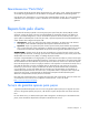
Customer self repair HP products are designed with many Customer Self Repair (CSR) parts to minimize repair time and allow for greater flexibility in performing defective parts replacement. If during the diagnosis period HP (or HP service providers or service partners) identifies that the repair can be accomplished by the use of a CSR part, HP will ship that part directly to you for replacement. There are two categories of CSR parts: • Mandatory—Parts for which customer self repair is mandatory.
• Obligatoire - Pièces pour lesquelles la réparation par le client est obligatoire. Si vous demandez à HP de remplacer ces pièces, les coûts de déplacement et main d'œuvre du service vous seront facturés. • Facultatif - Pièces pour lesquelles la réparation par le client est facultative. Ces pièces sont également conçues pour permettre au client d'effectuer lui-même la réparation.
In base alla disponibilità e alla località geografica, le parti CSR vengono spedite con consegna entro il giorno lavorativo seguente. La consegna nel giorno stesso o entro quattro ore è offerta con un supplemento di costo solo in alcune zone. In caso di necessità si può richiedere l'assistenza telefonica di un addetto del centro di supporto tecnico HP. Nel materiale fornito con una parte di ricambio CSR, HP specifica se il cliente deve restituire dei componenti.
stellen. Im Falle von Customer Self Repair kommt HP für alle Kosten für die Lieferung und Rücksendung auf und bestimmt den Kurier-/Frachtdienst. Weitere Informationen über das HP Customer Self Repair Programm erhalten Sie von Ihrem Servicepartner vor Ort. Informationen über das CSR-Programm in Nordamerika finden Sie auf der HP Website unter (http://www.hp.com/go/selfrepair).
Para obtener más información acerca del programa de Reparaciones del propio cliente de HP, póngase en contacto con su proveedor de servicios local. Si está interesado en el programa para Norteamérica, visite la página web de HP siguiente (http://www.hp.com/go/selfrepair). Servicio de garantía exclusivo de componentes La garantía limitada de HP puede que incluya un servicio de garantía exclusivo de componentes.
Garantieservice "Parts Only" Het is mogelijk dat de HP garantie alleen de garantieservice "Parts Only" omvat. Volgens de bepalingen van de Parts Only garantieservice zal HP kosteloos vervangende onderdelen ter beschikking stellen. Voor de Parts Only garantieservice is vervanging door CSR-onderdelen verplicht. Als u HP verzoekt deze onderdelen voor u te vervangen, worden u voor deze service reiskosten en arbeidsloon in rekening gebracht.
Customer self repair 10
Customer self repair 11
Customer self repair 12
Customer self repair 13
Illustrated parts catalog In this section System components ................................................................................................................................
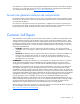
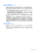
Item Description Spare part number Customer self repair (on page 4) 4 Fan module 399052-001 Mandatory1 5 7-segment display 399057-001 Optional2 6 Power supply 405914-001 Mandatory1 7 Riser board 399056-001 Optional2 8 Midplane 399051-001 Optional2 9 Backplane 454574-001 Optional2 10 Power on/off board with cable 399055-001 Optional2 11 Front UID board 399053-001 Optional2 12 Plastic cover — — * Not shown 1 Mandatory—Parts for which customer self repair is mandatory.
Optional: Opcional— componentes para los que la reparación por parte del usuario es opcional. Estos componentes también están diseñados para que puedan ser reparados por el usuario. Sin embargo, si precisa que HP realice su sustitución, puede o no conllevar costes adicionales, dependiendo del tipo de servicio de garantía correspondiente al producto. 3 No: No—Algunos componentes no están diseñados para que puedan ser reparados por el usuario.
Illustrated parts catalog 17
Removal and replacement procedures In this section Safety considerations.............................................................................................................................. 18 Power down the storage enclosure ........................................................................................................... 19 Remove the storage enclosure.................................................................................................................. 19 Access panel .......
• • • • • The leveling jacks are extended to the floor. The full weight of the rack rests on the leveling jacks. The stabilizing feet are attached to the rack if it is a single-rack installation. The racks are coupled together in multiple-rack installations. Only one component is extended at a time. A rack may become unstable if more than one component is extended for any reason.
4. Place the storage enclosure on a sturdy, level surface. Access panel To remove the component: 1. Power down the storage enclosure (on page 19). 2. Remove the storage enclosure (on page 19). 3. Lift the access panel latch and slide the access panel to the rear. 4. Remove the access panel. WARNING: To reduce the risk of personal injury from hot surfaces, allow the drives and the internal system components to cool before touching them.
You can replace hard drives without powering down the system. However, before replacing a degraded drive: • Open HP SIM and inspect the Error Counter window for each physical drive in the same array to confirm that no other drives have any errors. (For details, refer to the HP SIM documentation on the Management CD.) • Be sure that the array has a current, valid backup. • Use replacement drives that have a capacity at least as great as that of the smallest drive in the array.
3. Remove the hard drive. To replace the component: 1. Slide the drive into the cage until it clicks, locking the drive into place. 2. Close the lever. IMPORTANT: When the drive is inserted, the drive LEDs flash for 2 seconds to indicate that the drive is seated properly and receiving power. 3. As the drive begins to spin, be sure that the drive LEDs illuminate one at a time and then turn off together to indicate that the system has recognized the new drive.
Disconnect the power cord from the power supply, and then remove the component as indicated. To replace the component, reverse the removal procedure. Verifying proper operation After replacing the component, check the status LED. Hot-plug fan Verifying component failure Before replacing the component, verify component failure using the following methods: • Check the status LED ("Rear panel LEDs and buttons" on page 35). • Check the host log for errors.
Remove the component as indicated. To replace the component, reverse the removal procedure. Verifying proper operation After replacing the component, check the status LED. I/O module Verifying component failure Before replacing the component, verify component failure using the following methods: • Check the status LED ("Rear panel LEDs and buttons" on page 35). • Check the host log for errors.
4. Remove the module (3). NOTE: Use this same procedure to remove an I/O blank. To replace the component, reverse the removal procedure. Verifying proper operation After replacing the component, check the status LED. Front UID board Verifying component failure Before replacing the component, check the status LED ("Front panel LEDs and buttons" on page 34). To remove the components: 1. Power down the storage enclosure (on page 19). 2. Remove the plastic cover (1). 3.
4. Remove the plastic housing from the board (3). To replace the components, reverse the removal procedure. NOTE: For proper LED operation, when installing the new front UID board be sure that the component is properly lined up. Verifying proper operation After replacing the component, check the status LED.
9. Slide the board back to remove it from the guide, and then lift it out of the chassis (5). To replace the components, reverse the removal procedure. Verifying proper operation After replacing the component, verify proper operation using the following methods: • Check the heartbeat LED and fault LED status ("Front panel LEDs and buttons" on page 34). • Check the power supply LED status ("Rear panel LEDs and buttons" on page 35).
7. Lift the power UID board out of the chassis (4). To replace the component, reverse the removal procedure. Verifying proper operation After replacing the component, check the status LEDs. 7-segment display board Verifying component failure Before replacing the component, verify component failure using the following methods: • Check the LED display. • Check the host log for errors. No power to the 7-segment display board can also indicate riser board failure ("Riser board" on page 29).
5. Use a finger to slide out and remove the board (2). To replace the component, reverse the removal procedure. Verifying proper operation After replacing the component, check the status LEDs. Riser board Verifying component failure Before replacing the component, verify component failure using the following methods: • Check to see if power is applied to the 7-segment display board. • Check the host log for errors. To remove the component: 1. Power down the storage enclosure (on page 19). 2.
4. Loosen the thumbscrew (1), and then lift the board out of the chassis (2). To replace the component, reverse the removal procedure. Verifying proper operation After replacing the component, check to be sure power is applied to the 7-segment display board. Midplane Verifying component failure Before replacing the component, verify component failure using the following methods: • • Check the following component status LEDs: • Hard drives—Test with a known good hard drive.
10. Disconnect the cables from the midplane. 11. Loosen the two thumbscrews (1). 12. Push the board toward the back of the unit to disengage it from the backplane (2). 13. Tilt the midplane up and remove it from the chassis (3). To replace the components, reverse the removal procedure.
Before replacing the component, verify component failure using the following methods: • Check the hard drive status LEDs. Test with known good hard drives. • Check the host log for errors. To remove the components: 1. Power down the storage enclosure (on page 19). 2. Remove all hot-plug hard drives ("Hot-plug SAS or SATA hard drive" on page 20). 3. Remove the power supplies ("Hot-plug power supply" on page 22). 4. Remove the system fans ("Hot-plug fan" on page 23). 5.
Diagnostic tools In this section Integrated Management Log .................................................................................................................... 33 Array Diagnostic Utility ........................................................................................................................... 33 Integrated Management Log The IML records hundreds of events and stores them in an easy-to-view form. The IML timestamps each event with 1-minute granularity.
Component identification In this section Front panel LEDs and buttons ................................................................................................................... 34 Rear panel LEDs and buttons ................................................................................................................... 35 Rear panel components...........................................................................................................................
Rear panel LEDs and buttons Item Description Status 1 I/O module LED Green = System activity Amber flashing = Fault Off = No system activity 2 UID button/LED Blue = Identified Blue flashing = Active remote management Off = No active remote management 3 Heartbeat LED Green = System activity 4 System fan LED Green = Normal operation Off = No system activity Amber flashing = Fault condition Off = Fan unseated from connector or failed 5 System fault LED Amber = Fault condition Off = No fault c
Rear panel components Item Description 1 Power supply 1 2 Fan module 1 3 Dual 7-segment display board (for box ID numbering) 4 SAS in connector 5 SAS out connector 6 I/O module bay 7 For future use 8 Fan module 2 9 Power supply 2 Component identification 36
SAS and SATA device numbers SAS and SATA hard drive LEDs Item Description 1 Fault/UID LED (amber/blue) 2 Online LED (green) SAS and SATA hard drive LED combinations NOTE: Predictive failure alerts can occur only when the storage enclosure is connected to a Smart Array controller.
Online/activity LED Fault/UID LED (green) (amber/blue) Interpretation On, off, or flashing Alternating amber and blue The drive has failed, or a predictive failure alert has been received for this drive; it also has been selected by a management application. On, off, or flashing Steadily blue The drive is operating normally, and it has been selected by a management application. Amber, flashing regularly (1 Hz) A predictive failure alert has been received for this drive.
Specifications In this section Environmental specifications .................................................................................................................... 39 Storage enclosure specifications ..............................................................................................................
Acronyms and abbreviations ACU Array Configuration Utility ADG Advanced Data Guarding (also known as RAID 6) ADU Array Diagnostics Utility IML Integrated Management Log MSA Modular Smart Array MSA60 Modular Storage Array 60 RAID redundant array of inexpensive (or independent) disks SAS serial attached SCSI SATA serial ATA SCSI small computer system interface SIM Systems Insight Manager UID unit identification Acronyms and abbreviations 40
Index 7 illustrated parts catalog 14 Integrated Management Log (IML) 32 7-segment display 27 L A LEDs 33, 36 LEDs, troubleshooting 36 access panel 19 ADU (Array Diagnostic Utility) 32 B backplane, SAS 30 buttons 33 C component identification 33, 35 connectors 33 CSR (customer self repair) 4 customer self repair (CSR) 4 D device numbers 36 diagnostic tools 32 E electrostatic discharge 17 F fans 22 front panel LEDs 33 front UID board 24 H hard drive blanks 19 hard drive LEDs 36 hard drives 19, 36
W warnings 17 Index 42