
StorageWorks Modular Smart Array 20 Installation Overview


Selecting the Enclosure Environment
Before installing the enclosure in a rack, select a location that
meets the environmental requirements described in the
HP StorageWorks Modular Smart Array 20 User Guide.
For adequate airflow within the rack, use appropriate high-
airflow inserts in rack cabinet doors and observe industry-
standard practices for adequate spacing between racks or
rows of racks.
For more information about setting up the rack, refer to the rack
user guide.
Installing the Enclosure in a Rack
1. Remove the enclosure components to reduce the enclosure
weight and make it more manageable.
WARNING: The enclosure weighs 24 kg (53 lb) when full,
and 9 kg (20 lb) when the components have been
removed. Use two people to move an enclosure or to
install one in a rack.
2. Use the rack mounting template as a guide to mark where
in the rack the rails for the enclosure are to be located.
a. At the front of the rack, with the front of the template
facing you, align the lower edge of the template with
the bottom of the rack (or the top of the previous rack
component). Be sure that the lower edge of the
template is level.
b. Push the template tabs into the holes in the rack uprights
to hold the template in place.
c. Use a marker pen to indicate the holes in the rack
uprights into which the scissor-like locking latches are to
be inserted, as specified by the template.
d. Repeat these steps to mark the back of the rack, using
the information on the back of the template as a guide
to the required location of the locking latches in this
case.
3. If the holes in the rack uprights are round instead of
square, remove the standard pins from the rails and
replace them with the round-hole pins provided in the rack
mounting hardware kit.
WARNING: The pins in the rails are load-bearing. Do not
remove the pins except to replace them with the pins for
round-hole racks.
4. Identify the left (L) and right (R) rack rails by markings
stamped into the rails.
5. Slide the front end of the right rack rail toward the inside
front of the rack until the locking latch engages with the
marked hole in the front rack upright.
6. Extend the back end of the rail toward the inside rear of
the rack until the locking latch engages with the marked
hole in the rear rack upright.
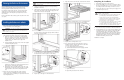
7. Loosen the locknut on the shipping bracket (1), and move
the bracket to the rearmost position on the rail (2).
8. Repeat steps 5 through 7 for the left rack rail.
9. Align the enclosure with the rails, and slide it into the rack.
10. Remove the mounting bracket covers (1), and tighten the
thumbscrews to secure the enclosure to the rack (2).
11. Replace the mounting bracket covers.
12. If you intend to move the rack while the enclosure is
installed, adjust the shipping brackets on each rail to
secure the enclosure in the rack.
a. Loosen the shipping bracket locknut (1).
b. Slide the bracket forward until it engages with the
enclosure chassis (2).
c. Tighten the locknut.
d. Repeat this procedure for the other rail.
Completing the Installation
1. Reinstall the components in the enclosure.
2. Connect the VHDCI connector on the controller module to
the output of an MSA1500 cs or to the external connector
of a sixth-generation Smart Array controller in a server.
3. Connect the AC input socket of each power supply unit to
separate AC power sources.
WARNING: To reduce the risk of electrical shock or
damage to the equipment:
• Do not disable the power cord grounding plug. The
grounding plug is an important safety feature.
• Plug the power cord into a grounded (earthed)
electrical outlet that is easily accessible at all times.
• Unplug the power cord from the power supply to
disconnect power to the equipment.
• Do not route the power cord where it can be walked
on or pinched by items placed against it. Pay
particular attention to the plug, electrical outlet, and
the point where the cord extends from the system.
4. Press the enclosure power button on the rear of the unit.
5. Confirm that the enclosure components are all functioning
normally by observing the condition of their status LEDs,
which should all be green. If the amber LED on any
component is illuminated, the component needs attention.
For detailed information about the meaning of different
LED illumination patterns, refer to the HP StorageWorks
Modular Smart Array 20 User Guide.
Installation is complete.