
HP MSA 2040 User Guide (723983-002, September 2013)


Controller enclosure—rear panel layout 15
MSA 2040 SAN controller module—rear panel components
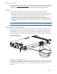
Figure 4 shows host ports configured with either 8/16 Gb FC or 10GbE iSCSI SFPs. The SFPs look
identical.
Refer to the LEDs that apply to the specific configuration of your Converged Network Controller ports.
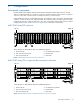
Figure 4 MSA 2040 SAN controller module face plate (FC or 10GbE iSCSI)
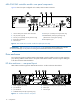
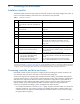
Figure 5 shows Converged Network Controller ports configured with 1 Gb RJ-45 SFPs.
Figure 5 MSA 2040 SAN controller module face plate (1 Gb RJ-45)
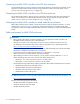
NOTE: See "MSA 2040 SAN" (page 11) for more information about Converged Network Controller
technology. For port configuration, see the “Configuring host ports” topic within the
HP MSA 2040 SMU Reference Guide or online help.
1 Host ports: used for host connection or replication
[see "Install an SFP transceiver" (page 89)]
2 CLI port (USB - Type B)
3 Service port 2 (used by service personnel only)
4 Reserved for future use
5 Network port
6 Service port 1 (used by service personnel only)
7 Disabled button (used by engineering only)
(Sticker shown covering the opening)
8 SAS expansion port
CACHE
CLI
CLI
LINK
ACT
6Gb/s
SERVICE−1SERVICE−2
PORT 1 PORT 2 PORT 3 PORT 4
157
3 4
6
8
2
= FC LEDs
= 10GbE iSCSI LEDs
CACHE
CLI
CLI
LINK
ACT
6Gb/s
SERVICE−1SERVICE−2
PORT 1 PORT 2 PORT 3 PORT 4
= 1 Gb iSCSI LEDs (all host ports use 1 Gb RJ-45 SFPs in this figure)
157
3 4
6
8
2
= FC LEDs