
HP MSA 2040 Cable Configuration Guide (729691-001, July 2013)

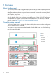
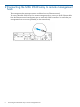

I/O modules A on the drive enclosures are shaded green. I/O modules B on the drive enclosures
are shaded red. Fault-tolerant cabling requires that you connect MSA 2040 controller A to I/O
module A of the first drive enclosure and cascade this connection on to I/O module A of the last
drive enclosure (shown in green). Likewise, you must connect MSA 2040 controller B to I/O module
B of the last drive enclosure and cascade this connection on to I/O module B of the first drive
enclosure (shown in red).
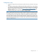
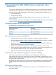
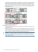
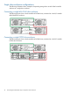
Straight-through cabling example
The following figure shows An MSA 2040 array connected to two D2700 drive enclosures using
straight-through cabling.
Straight-through cabling requires that you connect MSA 2040 controller A to I/O module A of the
first drive enclosure which is in turn connected to I/O module A of the last drive enclosure (shown
in green). MSA 2040 controller B is connected to I/O module B of the first drive enclosure which
is in turn connected to I/O module B of the last drive enclosure (shown in red).
IMPORTANT: Fault-tolerant cabling provides the highest level of fault-tolerance protection for the
array. Using straight-through cabling can sometimes provide increased performance in the array;
however, it also increases the risk of losing access to one or more enclosures in the event of an
enclosure failure or removal.
8 Connecting the MSA 2040 array to expansion drive enclosures