HP MPX200 Data Migration Planning Guide Abstract This guide provides end-to-end best practices for the use of HP MPX200 data migration service. This guide is intended for administrators responsible for implementing data migration projects. Administrators should be familiar with SAN development, configuration, and storage management.
© Copyright 2012 Hewlett-Packard Development Company, L.P. Confidential computer software. Valid license from HP required for possession, use or copying. Consistent with FAR 12.211 and 12.212, Commercial Computer Software, Computer Software Documentation, and Technical Data for Commercial Items are licensed to the U.S. Government under vendor's standard commercial license. The information contained herein is subject to change without notice.
Contents 1 Getting started ..........................................................................................4 Relationship between application data and physical storage..........................................................4 LUN access to a server..............................................................................................................5 Offline data migration...............................................................................................................
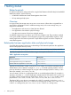
1 Getting started Related materials For reference information and procedures for using the DMS features of the HP utility for the MPX200 Multifunction Router, see the following: • HP MPX200 Multifunction Router Data Migration User Guide • HP mpx Manager help system Overview In a typical SAN, the storage array serves one or more servers.
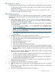
LUN access to a server Multipathing software installed on the server typically manages multiple paths to a LUN, for example: • A single storage array serves multiple servers and provides controlled access to the LUN, often called LUN presentation. • Multiple servers and storage arrays are present. Server access to a storage array is often controlled in the fabric by name server zoning. Offline data migration To perform a successful FC to FC offline data migration, follow these steps.
9. Acknowledge data migration jobs after they reach 100 percent complete. 10. Cut over the host server to the destination storage array by adjusting the Fibre Channel zones created in Step 3. 11. Update the LUN presentation from the destination array to the host server. 12. After data is migrated from one storage to another storage, perform the following steps as needed: • Update the multipathing software on the server, if necessary. • Adjust the mount point for the volume, if necessary.
4. 5. 6. 7. 8. 9. 10. 11. 12. 13. 14. Ensure that the MPX200 can discover all of the source arrays, destination arrays, and LUNs required for the migration project. Configure the source and destination storage array properties. For online remote data migration only, configure the data management LUN (DML). Configure LUN mapping to servers. Map source array LUNs to initiators or hosts. Configure presented targets to map source array ports with MPX200 FC1 and FC2 ports.
2 Inventory checklists Data migration checklists help the system administrator take inventory of all items affected by a data migration project. This chapter provides a list of servers and applications, and defines relationships of application data to LUNs and shows how LUNs are accessed through the server. The migration checklists also help to identify possible changes required on the server after migration. The tables in this chapter help you take proper inventory to plan data migration.
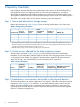
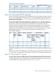
Table 4 Physical device information Server Application Mount point (if any) Volume Physical disk or raw device node LUN ID Step 4: List and create LUN ID mappings Create a list of LUNs containing the size and mapping information showing how they are seen by the server and the MPX200, as requested in Table 5 (page 9). Although a specific LUN can be presented at a different LUN ID to a server other than an MPX200, HP recommends that you use the same LUN ID, if possible.
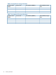
Table 6 Pre-migration FC zoning information FC Switch and IP address FC Zone name Zone members (WWPNs) Server, MPX200, storage name Table 7 Post-migration FC zoning information FC Switch and IP address 10 Inventory checklists FC zone name Zone members (WWPNs) Server, MPX200, storage name
3 Operating systems dependencies If the source array type is different from the destination array type, installation of the new multipathing software associated with the destination array might be required. CAUTION: Do not expose the destination LUNs to a server until the data migration is complete and server access to the source LUN is removed. Windows Windows operating systems offer two types of disks: basic disks and dynamic disks.
Citrix XenServer The MPX200 supports Citrix XenServer 6.0 for online data migration. Follow these guidelines when migrating LUNs presented to a Citrix XenServer: 12 • During migration, do not detach the virtual disk that is presented to a virtual machine running the application. • After migration activity is complete, and the virtual machine is ready for a downtime, first detach the virtual disk, and then detach the storage repository (SR). These steps ensure that the server has no access to the LUN.
4 Performance and downtime This chapter provides recommendations to improve performance and minimize downtime during data migration. Optimizing performance during data migration The MPX200 uses all available paths to a specified LUN and performs load balancing using all active optimized paths. HP recommends that you balance LUNs across paths on both array controllers.
7. 8. Use the MPX200 to create user-defined groups to assign the migration jobs related to the same server in a single group. Use the user interface wizard to configure migration jobs. During application downtime 1. 2. 3. 4. 5. 6. 7. Confirm with the storage administrator that the application and server are down, and that the server no longer has access to the storage under migration.
5 Support and other resources Contacting HP For worldwide technical support information, see the HP support website: http://www.hp.com/support Before contacting HP, collect the following information: • Product model names and numbers • Technical support registration number (if applicable) • Product serial numbers • Error messages • Operating system type and revision level • Detailed questions Related information For additional information, see the following websites: • http://www.hp.
Table 8 Document conventions (continued) Convention Element Monospace text • File and directory names • System output • Code • Commands, their arguments, and argument values Monospace, italic text • Code variables • Command variables Monospace, bold text IMPORTANT: NOTE: TIP: 16 Emphasized monospace text Provides clarifying information or specific instructions. Provides additional information. Provides helpful hints and shortcuts.
6 Documentation feedback HP is committed to providing documentation that meets your needs. To help us improve the documentation, send any errors, suggestions, or comments to Documentation Feedback (docsfeedback@hp.com). Include the document title and part number, version number, or the URL when submitting your feedback.
A Checklist examples This appendix provides examples of completed data migration checklists. These examples depict a scenario where a customer is upgrading from an old EMC CX3-20 storage array to an HP EVA 4400 storage array. Three applications and servers are using the CX3-20 array. Each of these three servers has a different operating system.
Table 11 Example: physical device information Server Application Mount point (if any) Volume Physical disk or raw device node HR-Dept Sharepoint F:\Sharepoint F:\ Disk0, Disk1 (Dynamic Disks) 0, 1 iPortal Apache Web Server /data/webinfo /dev/sdb /dev/sdb 0 Sales Oracle /home/oracle /dev/vg-2/ vol2 /dev/rdsk/ c0t1d0 /dev/rdsk/ c0t1d1 /dev/rdsk/ c0t1d2 0, 1, 2 LUN ID List and create LUN ID mappings Table 12 (page 19) shows LUNs presented to the MPX200 at LUN IDs that are different from
Table 13 Example A: pre-migration FC zoning information (continued) FC Switch and IP address FC Zone name Zone members (WWPNs) Server, MPX200, storage name 21-00-00-C0-DD-C0-55-58 iPortal: P2 21-00-00-C0-DD-C0-60-67 Sales: P2 50-06-01-61-41-E0-18-94 SRC-Array-ABC: P2 50-06-01-63-41-E0-18-94 SRC-Array-ABC: P4 Table 14 (page 20) shows new FC zone information to configure MPX200 for data migration and to migrate the data. The MPX200 FC ports are configured with source and destination arrays.
B Assigning LUNs to the MPX200 for data migration For successful completion of data migration, assign source and destination LUNs to the MPX200 using storage array management tools. The MPX200 appears as a host to the array controller. When you register the MPX200 port WWNs, you must set the correct attributes. Ensure that you register all WWNs belonging to a specific VP group under a single host entity.
4. In the left pane, click VOLUME MANAGEMENT, select volume mapping > manage host list. Figure 2 (page 22) shows the WWPN of the data migration appliance in the right pane. Figure 2 Viewing WWPNs in Storage Management Utility 5. 6. 7. 8. 22 In the Manufacturer Nickname box, enter DM-Host. To accept and save the changes, click Update. In the left pane, select VOLUME MANAGEMENT > volume mapping, and then select map hosts to volume.
Figure 3 Selecting LUNs in Storage Management Utility 9. In the Assign Host Access Privileges table, select the DM-Host in the Host WWN - Name list, and enter the appropriate, planned LUN ID. 10. To accept and save the LUN assignment, click Map it. 11. Refresh the data migration user interface to see if the LUN assignment reflects properly, and that the appropriate array entity appears under FC Array. (You may need to click the Refresh button several times to correctly reflect the changes.
Figure 4 Configure available devices 3. In the right pane under Common Tasks, select Selective Storage Presentation > Enable. A list of the WWPNs seen by the MSA controller appears, as shown in Figure 5 (page 24). Figure 5 Entering a connection name 4. 5. 24 Enter DM-Host as the connection name for the data migration appliance WWPN. From the list box, select Windows as the host mode value, as shown in Figure 6 (page 25).
Figure 6 Selecting the host mode 6. Select the LUNs to be assigned to the DM-Host by checking the box associated with the previously planned LUNs, as shown in Figure 7 (page 25). Figure 7 Selecting LUNs 7. 8. To accept and save the LUN assignment, click OK. Refresh the data migration user interface to see if the LUN assignment is reflected properly, and that the appropriate array entity appears under FC Array. (You may need to click the Refresh button several times to correctly reflect the changes.
1. Create a host entity for router ports on the array. This step is needed to map the LUNs to the routers. a. In the 3PAR Inform Management Console, select Hosts in the left pane, and click Create Host. b. On the Create Host wizard, General page (see Figure 8 (page 26)), enter a Name for the host, and in the Persona box, select the appropriate operating system as the host type. Click Next to continue. Figure 8 Creating a host: General c.
2. Create a CPG, which is a buffer pool of logical disks that you use to create LUNs (virtual volumes). CPGs have the following qualities: • A CPG is a thin-provisioned entity. Physical spaces (chunklets) are assigned when virtual volumes are created (depending on whether the LUN is thick- or thin-provisioned). • You can create a CPG for any specific disk type and speed. • You can assign a RAID group to the CPG to ensure that any LUN (virtual volume) created using this CPG has an assigned RAID level.
Figure 10 Creating a CPG: General 3. 4. 3. 28 In the Create CPG wizard, Summary page, review your settings and then either click Prev to go back and change the selections, or click Finish to create the CPG. In the left pane under Provisioning, click CPGs to view the newly created CPG in the right pane. Total capacity is shown as 0.00 because no virtual volumes have been created on this CPG. Create virtual volumes (LUNs) using any of the available CPGs.
v. Click Next to continue. Figure 11 Creating a Virtual Volume: General d. e. f. Select for the CPG copy space. (Copy space creates a backup of the same virtual volumes, which you can store on a different CPG.) Click Next to review the virtual volume configuration. On the Create Virtual Volume wizard Summary page, review your settings and then either click Prev to go back and change the selections, or click Finish to create the virtual volume.
4. Map a virtual volume to the host as follows: a. In the 3PAR Inform Management Console, right-click Hosts in the left pane, and then on the shortcut menu, click Export Volume. b. In the Export Virtual Volume wizard General page, click one of the following, and then click Next: c. • Click the Virtual Volume button, and select one or more volumes from the list. • Click the Virtual Volume Set button; all virtual volumes in the set are selected.
Assigning LUNs from an HP EVA 4/6/8000 Series Array Storage vendor HP Array model EVA 4/6/8000 series arrays LUN assignment tool Command View user interface To assign LUNs: 1. Perform zoning: a. Connect the FC ports of the data migration appliance to a switch where the storage controller ports are also logged. b. Use switch management tools to create a zone, DM_Host_EVA. c. In this zone, add the WWPN of the data migration appliance FC ports and storage controller ports. d.
Figure 14 Opening HP Command View EVA 3. 4. 5. 32 In the left pane, double-click the array that you want to manage. This expands the nodes under the selected array. In the left pane, click the Hosts node. Complete the Add a Host information in the right pane (see Figure 15 (page 33)): a. Under Basic Settings in the Name box, enter DM-Host. b. Under Port World Wide Name, click the WWN of the data migration appliance. c. Under Operating System, click Microsoft Windows. d. Click the Add host button.
Figure 15 Adding a Host 6. If you have a multipath configuration, add the second router port to the DM-Host entity (see Figure 16 (page 33)): a. Under the Hosts tree in the left pane, select the DM-Host node. b. In the right pane, select the Ports tab. c. On the Add a Host Port page, select a WWN, and click the Add port button. Figure 16 Adding a second host port 7. Present virtual disks (see Figure 17 (page 34)): a. In the left pane, double-click the Virtual Disks node. b.
Figure 17 Presenting Vdisks 8. Refresh the data migration user interface to see if the LUN assignment is reflected properly, and that the appropriate array entity appears under FC Array. (You may need to click the Refresh button several times to correctly reflect the changes.) Assigning LUNs from an HDS Array Storage vendor HDS Array model AMS/WMS series arrays LUN assignment tool Storage Navigator Modular user interface To assign LUNs: 1. Perform zoning: a.
Figure 18 Changing to Management Mode 4. 5. 6. Under Array Unit, double-click the name of the array to manage. The Array System Viewer window opens. In the left pane, select the Logical Status tab. In the left pane, right-click the port of the array that has been zoned with the data migration appliance, and click Add New Host Group (see Figure 19 (page 36)).
Figure 19 Selecting a port for new host group 7. 8. In the Host Group dialog box, enter DM-Host in the Name box, and then click OK. In the Array System Viewer left pane under Host Groups, click the + sign next to the port to expand the newly-created DM-Host group entity. Three nodes are listed: Options, Logical Unit, and WWN, as shown in Figure 20 (page 36).
9. In the left pane, click the Options node, and at the bottom of the right pane, click Simple Setting. 10. Complete the Simple Setting dialog box: a. Next to Platform, select Windows2003. b. Keep the other settings as default. c. To save the changes, click OK. 11. In the Array System Viewer dialog box, under the DM-Host group, click the WWN node. Then, at the bottom of the right pane, click Modify WWN Information (see Figure 21 (page 37)). Figure 21 Array System Viewer 12.
14. Complete the Modify Mapping dialog box (see Figure 22 (page 38)): a. Under H-LUN / Available Logical Units, select an appropriate LUN. b. c. Click the (up arrow) to map the LUN to the DM-Host group. To accept and save the LUN assignment, click OK. Figure 22 Modify Mapping 15. Refresh the data migration user interface to see if the LUN assignment is reflected properly, and that the appropriate array entity appears under FC Array.
2. Using Internet Explorer, open the Navisphere utility using the IP assigned to the storage controller. The Enterprise Storage dialog box opens (see Figure 23 (page 39)). Figure 23 Viewing Enterprise Storage 3. 4. 5. Select the appropriate storage array, right-click the array name, and click Connectivity Status. Select the WWPN associated with the data migration appliance, and then click Register. Complete the Register Initiator Record dialog box (see Figure 24 (page 40)): a.
Figure 24 Registering Initiator Record 6. 40 Create a storage group to add to the newly-registered DM-Host entity (see Figure 25 (page 41)): a. In the Enterprise Storage window, Storage page, right-click the Storage Groups node. b. Click Create Storage Group. c. In the Create Storage Group dialog box, enter DM-Host as the Storage Group Name. d. To save the changes, click either OK or Apply. The new DM-Host storage group is listed under the Storage Groups tree in the main window.
Figure 25 Creating Storage Group 7. Add the DM-Host host entity to the DM-Host storage group entity (see Figure 26 (page 42)): a. Under the Storage Groups node, right-click DM-Host. b. Click Connect Hosts. c. In the DM-Host: Storage Group Properties dialog box, select the Hosts tab. d. On the Hosts page under Available Hosts, select the DM-Host host entity. e. f. Click the (right arrow) button to move DM-Host to the right pane’s Host to be Connected box. To save the changes, click either OK or Apply.
Figure 26 Adding DM-Host to Storage Group NOTE: Before assigning LUNs, you must register as a single host entity all router ports that will access the same LUNs as a single host entity. If you add a new router port to an existing host entity, that port will not appear as a new path for the assigned LUNs in the router’s show luninfo command output. 8. 42 Add LUNs to the DM-Host storage group entity (see Figure 27 (page 43)): a. Under the Storage Groups tree, right-click DM-Host. b.
Figure 27 Adding LUNs to DM-Host 9. Refresh the data migration user interface to see if the LUN assignment is reflected properly, and that the appropriate array entity appears under FC Array. (You may need to click the Refresh button several times to correctly update the display.) Assigning LUNs from an EMC Symmetrix DMX-4 array Storage vendor EMC Array model Symmetrix DMX-4 arrays LUN assignment tool EMC Symmetrix Management Console To assign LUNs: 1.
a. b. c. d. Click Initiators. Under Available Initiators, select one or more initiators and click Add to move your selections to the Selected Initiators table. Select the Refresh VCMDB check box. Click Next to continue.
8. Under 4. Select Ports, follow these steps (see Figure 29 (page 45)): a. Under Available Ports, select one or more ports and click Add to move your selections to the Selected Ports table. b. Click Next to continue. Figure 29 Selecting ports 9. In the right pane under 5. Select Devices, follow these steps (see Figure 30 (page 46)): a. For Group Type, select Ungrouped. b. Under Available Devices, select one or more devices, and click Add to move your selections to the Selected Devices table. c.
Figure 30 Selecting devices 10. In the right pane under 6. Summary, review your masking selections and either click Back to modify a previous step, click Next to continue, or click Finish to close the masking wizard and return to the Tasks page of the EMC Symmetrix Management console. A message box informs you that the Symmetrix device masking session completed successfully.
Figure 31 Selecting host to define 5. Complete the Define Host wizard (see Figure 32 (page 47)): Figure 32 Defining the host a. b. c. d. Under Specify name of host, enter DM-Host as the name for the data migration appliance. In the Known HBA host port identifiers box, click the WWPN of the data migration appliance. Click Add to move the selected WWPN to the Selected HBA host port identifiers/aliases box. Click Edit, and, in the Edit Identifier/Alias dialog box, enter an alias for the WWPN.
e. f. Click Next. In the Specify Host Type window (see Figure 33 (page 48)) under Host type (operating system) , click Windows 2000/Server 2003 Non-Clustered. Figure 33 Selecting host operating system 6. 7. 8. 48 g. Click Next. On the Subsystem Management window, in the left pane’s Mapping View page, click either Undefined Mappings or the host group/host that currently has access to the LUNs that need to be part of data migration jobs.
Figure 34 Defining additional mapping 9. Refresh the data migration user interface to see if the LUN assignment is reflected properly, and that the appropriate array entity appears under FC Array. (You may need to click the Refresh button several times to correctly reflect the changes.) Assigning LUNs from an IBM V7000 Array Storage vendor IBM Array model IBM Storwize V7000 disk system LUN assignment tool IBM Storwize V7000 management utility To assign LUNs: 1. Perform zoning: a.
2. 3. 4. In a Web browser, open the IBM Storwize V7000 management tool by entering the IP address of the array controller. In the left pane, select Hosts > Ports by Host. In the right pane, complete the Add a Host information: a. Click the New Host button, and under Choose the Host Type, click the Fibre-Channel Host icon, as shown in Figure 35 (page 50). Figure 35 Creating the FC host b. c. d. Optional: Enter the host name in the Host Name box.
d. Click the Create Host button. Figure 36 Creating a host The newly created host is now listed with the registered WWPNs under Host Filter, as shown in Figure 37 (page 51).
6. Present volumes to the router: a. In the left pane, select Volumes, point to All Volumes, and select the volume to be presented. b. In the Volumes by Pool window under Status, click Map to Host. c. On the small Modify Mappings dialog box, select the host from the list, and click Next. The large Modify Mappings dialog box right pane shows the volume with the SCSI ID, name, and the user identifier (UID). d. 7. e. To a. b. c.
a. b. c. In the left pane, expand the Real-time manager tree branch, and click Volume groups. In the right pane, complete the Volume groups: Real-time window: i. Under Select storage unit, select the array. ii. On the action menu, click Create. Complete the Define volume group properties window (see Figure 39 (page 53)): i. Under Nickname, enter a user-defined name for the new group. ii. Under Accessed by host types, select the Win2003 check box. All other applicable host types are automatically selected.
Figure 40 Defining volume characteristics d. Complete the Define volume properties window (Figure 41 (page 54)): i. In the Quantity box, enter the number of volumes to be created. ii. In the Size (GB=2^30) box, enter the size of the new volumes. iii. Optional: Click the Calculate buttons to determine the total available capacity for creating volumes.
Figure 42 Creating volume nicknames f. 5. 6. 7. On the Verification window, review and confirm that the settings are correct, and click Finish. On the Create open systems volumes: Real-time window, view the task attributes, and then click Close and View summary. Define a real-time host group: a. In the left pane, expand the Real-time manager tree branch, and then under Manage hardware, click Host systems. b. In the right pane, complete the Host systems: Real-time window: i.
f. Click Next to continue. 8. On the Define host WWPN window, select the WWPN for each port, and then click OK. 9. Complete the Specify storage units window: a. Select a unit under Available storage units. b. Click Add to move it to Selected storage units. c. Click Next to continue. 10. Complete the Modify Host System window (see Figure 44 (page 56)): a. Under Identifier, select the host that you created in Step 9. b.
2. 3. In a Web browser, open the NetApp FilerView tool by entering the IP address of the array controller. Create an initiator group: a. In the left pane under LUNs, select Initiator Groups and then click Add. b. Complete the Add Initiator Group area in the right pane (see Figure 45 (page 60)). Figure 45 Adding Initiator Group c. d. e. f. In the Group Name box, enter DM_host. For host Type, select FCP. For Operating System, select Microsoft Windows.
a. In the left pane under LUNs, click Manage to open the Manage LUNs area in the right pane (see Figure 46 (page 58)). Figure 46 Managing LUNs b. c. In the Maps Group : LUN ID column, click the LUN to be presented to the DM_host. In the LUN Map pane (see Figure 47 (page ?)), click Add Groups to Map. Figure 47 Mapping LUNs d. e. f. 58 Under Initiator Group, select the DM_host initiator. Under LUN ID, enter the ID at which this LUN is presented to the DM_host. To save this mapping, click Apply.
5. Verify the updated assignment: a. In the left pane under LUNs, click Manage to open the Manage LUNs area in the right pane. b. In the Maps Group : LUN ID column, confirm the new DM_host assignment (see Figure 48 (page 59)). Figure 48 Verifying LUN mapping Assigning LUNs from a NetApp FAS2040 system using NetApp System Manager Storage vendor NetApp Array model FAS2040 system LUN assignment tool NetApp System Manager To assign LUNs: 1. Perform zoning: a.
Figure 49 Adding an Initiator Group 6. 7. On the Initiator Groups page under Initiator IDs, click the Add button. Complete the Add Initiator ID dialog box (see Figure 50 (page 60)): a. For Group Type, select FCP. b. For Group Name, select the user-defined name that you specified in Step 5 (DM-Appliance, for example). c. In the Initiator Name box, type the WWPN of the appliance. d. Click Add. Figure 50 Adding an Initiator ID 8. Repeat Step 7 to add the WWPN of each virtual port.
9. Present the LUN: a. In the left pane, expand the tree, and then under the Storage node, click LUNs. b. In the right pane, select the LUN Management tab. c. On the LUN Management page, right-click the volume that you want to present to the data migration appliance, and click Properties. d. Complete the LUN Volume xx Properties page (see Figure 51 (page 61)): i. Select the Initiators tab. ii. Under Known initiator hosts, select the initiator group name that you specified in Step 5. iii.
3. 4. 5. Enter the administrator user name and password, and click Login. To view the virtual server configuration, in the left pane under VSERVER, click manage. Because the array can manage multiple Vservers, be sure to select the Vserver that owns the LUNs that are part of the data migration jobs. To create a volume: a. In the left pane under VOLUME, click manage. b. On the Volume page, click create. c. Complete the volume information (see Figure 52 (page 62)): i. Select the appropriate Vserver Name. ii.
Figure 53 Creating a LUN 7. 8. d. Verify that the LUN was created successfully, and then click Return to Table. e. Verify that the LUN is configured correctly. Repeat the preceding step, as needed, to create additional LUNs. To create an initiator group: a. In the left pane under LUN, click igroup. b. On the Igroup Table page, click create. c. Complete the igroup information (see Figure 54 (page 64)): i. Select the appropriate Vserver Name. ii. Enter the Igroup Name. iii. For Protocol, select mixed. iv.
Figure 54 Creating an initiator group 9. d. Verify that the igroup is configured correctly. To map a LUN to a host igroup: a. In the left pane under LUN, click manage. b. On the LUN Table page, select a LUN, and click map. c. Complete the LUN map information (see Figure 55 (page 64)): i. Select the appropriate Vserver Name. ii. Enter the LUN Path, Initiator Group Name, and LUN ID in the appropriate boxes. iii. Click map. Figure 55 Creating a LUN Map 10. To map additional LUNs, repeat the preceding step.
1. 2. 3. 4. Perform zoning: a. Connect the FC ports of the data migration appliance to a switch where the storage controller ports are also logged. b. Use switch management tools to create a zone, DM_Host_netapp. c. In this zone, add the WWPN of the data migration appliance FC ports and storage controller ports. d. Save the zoning information and activate the new zoning configuration. Open the SANtricity ES tool.
e. Complete the Customize Advanced Volume Parameters (Create Volume) wizard window (see Figure 57 (page 66)): i. Under Volume I/O characteristics type, click File system (typical). ii. Under Preferred controller ownership, click Slot A. iii. Click Next. Figure 57 Creating a Volume: Advanced Parameters f. 5. 66 On the Specify Volume-to-LUN Mapping (Create Volume) wizard window, select Map later using the Mappings View and then click Finish. g.
vi. Click Next. Figure 58 Specifying host port identifiers e. f. g. On the Specify Host Type (Define Host) wizard window, select the Host type (operating system) as Windows Server 2003/Server 2008 Non-Clustered, and click Next. On the Host Group Question (Define Host) wizard window, select No - this host will NOT share access to the same volumes as other hosts > Next. On the Preview (Define Host) wizard window, review the current host definition.
6. Map a volume: a. In SANtricity ES, select the Setup tab. b. Under Storage Array Configuration, click Map Volumes. c. Complete the Define Additional Mapping dialog box (see Figure 59 (page 68)): i. Select the Host group or host. ii. Select the Logical unit number (LUN) (0 to 255). iii. Click the Volume Name. iv. Click Add. Figure 59 Mapping a Volume d. e. Repeat the preceding step for any additional LUNs. When all LUNs are mapped, click Close.
To assign LUNs: 1. Perform zoning: a. Connect the FC ports of the data migration appliance to a switch where the storage controller ports are also logged. b. Use switch management tools to create a zone, DM_Host_Emprise5000. c. In this zone, add the WWPN of the data migration appliance FC ports and storage controller ports. d. Save the zoning information and activate the new zoning configuration. 2. In a Web browser, open the Emprise 5000 Management tool by entering the array management IP address. 3.
Assigning LUNs from a Xiotech Magnitude 3D 4000 array Storage vendor Xiotech Corporation Array model Magnitude 3D 4000 arrays LUN assignment tool ICON Manager 3.3 NOTE: The Magnitude 3D 4000 array requires that the ICON Manager 3.3 tool be installed on the host. To assign LUNs: 1. Perform zoning: a. Connect the FC ports of the data migration appliance to a switch where the storage controller ports are also logged. b. Use switch management tools to create a zone, DM_Host_XiotechMagnitude3D_4000. c.
e. 6. 7. 8. 9. On the Configure Another Server Initiator? window, click Yes to configure a second server initiator, or No to stop configuring servers. f. Click Next to continue. g. On the wizard’s Done window, click Finish. In the Group Servers dialog box, click Close. In the ICON Manager left pane, click Server View. In the middle pane, ensure that the Server View lists the newly created volume. Assign the volume to the initiator: a. In the Server View pane, select the newly created volume. b.
1. 2. 3. 4. Perform zoning: a. Connect the FC ports of the data migration appliance to a switch where the storage controller ports are also logged. b. Using switch management tools, create a zone, DM_Host_DX440. c. In this zone, add the WWPN of the data migration appliance FC ports and storage controller ports. d. Save the zoning information and activate the new zoning configuration. In a Web browser, open the ETERNUS SF utility by entering the IP address of the array controller.
Figure 64 Creating a controller adapter port group 6. Create a host group (see Figure 65 (page 73)): a. In the left pane, click Host Group. b. In the right pane, click the FC/FCoE Host. c. In the New Group Name box, enter a name for the data migration appliance. d. Select all WWNs that belong to this data migration appliance’s VPG. e. To detect the connected ports, click Rediscover.
7. Create a host affinity group (see Figure 66 (page 74)): a. On the left side, click Connectivity. b. In the right pane, click Create Host Affinity. c. In the next window, select the previously-created Host Group, CA Port Group, and LUN Group. NOTE: This procedure assumes that a LUN group has already been created. A LUN group contains all of the LUNs and the LUN to Host LUN definition to be used for a specific host.
Figure 67 Creating a host response 5. Create a host (see Figure Figure 68 (page 76)): a. In the left pane, click Host Interface Management and then click Set Host WorldWideName(s). b. In the right pane under Add WNN, create a host by entering the host Name and selecting the WWN. c. Select the CA and port to which the data migration appliance is connected. d. To refresh the visible WWNs and select the correct entry, click Collect. e. Select the WWPN of the data migration appliance’s FC ports.
Figure 68 Setting the host WWN 76 Assigning LUNs to the MPX200 for data migration
6. Create a host affinity group: a. In the left pane, click Host Interface Management and then click Allocate Host-Infinity Group. b. In the right pane under Select a CA, click the port on which the data migration appliance WWPN is available (for which host was created in Step 5), and click Set (see Figure 69 (page 77).) Figure 69 Allocating a host affinity group c.
Assigning LUNs from a Dell Compellent Array Storage vendor Dell Array model Dell Compellent Storage Center LUN assignment tool Dell Compellent Storage Center To assign LUNs: 1. Perform zoning: a. Connect the FC ports of the data migration appliance to a switch where the storage controller ports are also logged. b. Using switch management tools, create a zone, DM_Host_DC. c. In this zone, add the WWPN of the data migration appliance FC ports and storage controller ports. d.
6. On the Create Server confirmation dialog box (Figure 72 (page 79)), verify your server and Host Bus Adapter selections, and then click Create Now to continue. Figure 72 Confirming server creation 7. 8. 9. In the left pane under the Servers node, select the newly created host server, and click the Map Volume to Server button. In the Map Volume to Server dialog box, select the volume (New Volume 1, for example) to be mapped, and then click Continue.
10. In the left pane under the Servers node, select the newly created host, and in the right pane: a. Click the Volumes button to view the list of volumes mapped to that host. b. Click the Properties button to view the general host properties on the Server Properties dialog box (Figure 74 (page 80)). Figure 74 Viewing host server properties c. Click OK to close the dialog box.
Figure 75 Group Manager Utility 3. In the Activities list under Getting Started, click Create volume.
4. Complete the Create Volume wizard as follows: a. On Step 1 – Volume Settings, enter a volume name, select the default storage pool, and then click Next (see Figure 76 (page 82)). Figure 76 Creating a volume — step 1 b. On Step 2 – Space, specify the volume space, and then click Next (see Figurexx). Figure 77 Creating a volume — step 2 c. 82 On Step 3 – iSCSI Access (see Figure 78 (page ?)), do the following: i. Click Restricted access. ii.
• Limit access to iSCSI initiator name. Enter the iSCSI initiator name in the box. iii. Under Access Types, click Set read-write. iv. Click Next. Figure 78 Creating a volume — step 3 5. 6. On Step 4 – Summary, review your volume settings and then click Finish to create the volume or Back to view and change any of the settings. Review the settings of the newly created volume as follows: a. In the tree in the left pane, expand the Volumes branch, and then locate the volume. b.
Glossary A API Application Programming Interface. A specification intended to be used as an interface by software components to communicate with each other. array A storage system that contains multiple disk or tape drives. A disk array, for example, is differentiated from a disk enclosure in that the array has cache memory and advanced functionality, like RAID and virtualization. Components of a typical disk array include disk array controllers, cache memories, disk enclosures, and power supplies.
F fabric A fabric consists of cross-connected FC devices and switches. FC Fibre Channel. High-speed serial interface technology that supports other higher layer protocols such as SCSI and IP; FC is primarily used in SANs. FC over Ethernet See FCoE. FCF Fibre Channel Forwarder. FCoE FC over Ethernet. An encapsulation of FC frames over Ethernet networks. This allows FC to use 10 Gigabit Ethernet networks while preserving the FC protocol. FDX Full–Duplex.
J jumbo frame A large IP frame used in high-performance networks to increase performance over long distances. Jumbo frames are typically 9,000 bytes for GbE, but can refer to anything over the IP MTU (1,500 bytes on an Ethernet). L LIP Loop Initialization Process. The initialization process in an arbitrated loop that occurs when the loop is powered up or a new device is added. One function of a LIP is to assign addresses. All data transmission on the loop is suspended during a LIP.
point-to-point Also FC-P2P. Two FC nodes directly connected (not in a loop). port An access point in a device where a link attaches. POST Power-On Self Test. Diagnostics that the router performs at start-up. R RAID Redundant Array of Independent Disks. A storage technology that combines multiple disk drive components into a logical unit. Data is distributed across the drives in one of several ways called RAID levels. RISC Reduced Instruction Set Computer.
VPG Virtual Port Group (or VP Group). An RCLI software component used to create logical FC adapter initiator ports on the fabric. W WWNN World Wide Node Name. Unique 64-bit address assigned to a device. WWPN World Wide Port Name. Unique 64-bit address assigned to each port on a device. One WWNN may contain multiple WWPN addresses. WWULN World Wide Unique LUN Name. WWULN identifiers for SCSI devices are read from page 80 and page 83 of your SCSI block device as based on the SCSI standard.
Index A Accept Target I/O (ATIO), 84 API, 84 Application Programming Interface (API), 84 array, 84 ATIO, 84 B bandwidth, 84 C CA, 84 CDB, 84 Challenge Handshake Authentication Protocol (CHAP), 84 CHAP, 84 CLI, 84 CmdSN, 84 Comma-Separated Value (CSV), 84 Command Descriptor Block (CDB), 84 Command Line Interface (CLI), 84 Command Sequence Number (CmdSN), 84 Common Provisioning Group, 84 contacting HP, 15 Controller Adapter (CA), 84 conventions document, 15 CPG, 84 CRC, 84 CSV, 84 Cyclic Redundancy Check (C
loopback, 86 LUN, 86 LVM, 86 M MAC address, 86 Management Information Base (MIB), 86 Maxium Transmission Unit (MTU), 86 MGMT, 86 MIB, 86 mount point, 86 MTU, 86 multipathing software, 86 N Network Time Protocol (NTP), 86 Non-Volatile Random Access Memory (NVRAM), 86 NTP, 86 NVRAM, 86 T target, 87 Target Process Block (TPB), 87 Target System Identifying Handle (TSIH), 87 TCP, 87 technical support HP, 15 Telnet, 87 TPB, 87 Transmission Control Protocol (TCP), 87 TSIH, 87 typographic conventions, 15 U Univ