
Building Disaster Recovery Serviceguard Solutions Using Metrocluster with Continuous Access for P9000 and XP A.11.00

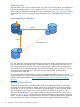

data replication to the third site (Site3) by copying only delta changes. This avoids a single point
of failure for data replication following a site outage.
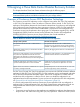
Another advantage with the Tri-Link configuration is, you can balance the replication load to Site3
by using different replication link for different applications. For example, for some applications,
data can be replicated to Site3 over the link between Site1 and Site3, whereas for other applications
data can be replicated over the link between Site2 and Site3. This kind of flexibility is not available
in the Bi-Link configuration.
One advantage of Bi-Link configuration over Tri-Link configuration is that in a Bi-Link configuration
Continuous Acess link must be configured to Site3 from only one site in the Metrocluster. Whereas
in a Tri-Link configuration, you must configure Continuous Access links from both the sites in the
Metrocluster. However, HP recommends to use Tri-Link configuration as it avoids single point of
failure for data replication following a site outage.
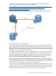
HP Storage 3DC Replication Topologies
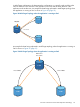
In a P9000 or XP 3DC design there are two replication topologies available: Multi-Hop and
Multi-Target. In addition, the configuration can switch between these two topologies at any time
during normal operation of a P9000 or XP 3DC solution. The main characteristics of the topology
are determined by two factors: Where data enters the configuration (that is, on which data center
is the application running) and in what direction the data flows.
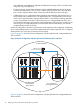
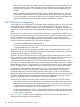
In Multi-Hop topology, the data enters the system on one end, is replicated to the next available
storage array, and from there it is replicated to the last storage array. In most cases, starting point
of the configuration indicates the site or host that runs the application under normal conditions,
with the second site being the automated cluster failover node and the third site being the manual
failover long-distance node. An example for data being replicated in Multi-Hop topology when
the application is running at Site1 is shown in Figure 28 (page 94).
Figure 28 Multi-Hop Topology when the application is running at Site1
Site 1
Data enters
the system
Site 2
Flow of data
Site 3
S-VOL
P-VOL
S/P-VOL
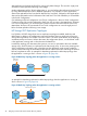
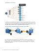
An example for data being replicated in Multi-Hop topology when the application is running at
Site2 is shown in Figure 29 (page 94).
Figure 29 Multi-Hop Topology when the application is running at Site2
Site 1
Data enters the system
Site 2
Flow of data
Site 3
S-VOL
S/P
VOL
P-VOL
94 Designing a Three Data Center Disaster Recovery Solution