
Building Disaster Recovery Serviceguard Solutions Using Metrocluster with Continuous Access for P9000 and XP A.11.00

Configure Oracle RAC in the recovery cluster.a.
b. Configure the Site Controller Package in the recovery cluster.
c. Configure the Site Safety Latch Dependencies in the recovery cluster.
7. Configure Continentalclusters.
8. Configure a Continentalclusters Recovery Group.
Configuring the Primary Cluster
Create a Metrocluster with two sites configured in the Serviceguard cluster using the nodes in the
first data center (DC1) as part of one site and the nodes in the second data center (DC2) as part
of the other site using the procedure described in the section “Configuring Metrocluster with sites”
(page 195) in chapter 7. This Metrocluster acts as a primary cluster in the Continentalclusters
environment.
Configure the Recovery Cluster
A Serviceguard cluster must be created with a single site configured. This site must comprise all
nodes in the cluster. This cluster acts as a recovery cluster in the Continentalclusters environment.
In this example, a Serviceguard cluster with a single site is created using all nodes from Site 3.
Complete the following steps to create a Serviceguard cluster with a single site configured:
1. Run the cmquerycl command to create a cluster configuration from any node.
2. Edit the created cluster configuration file to specify a site configuration.
Following is a sample configuration file:
SITE_NAME <Site 3 site name>
NODE_NAME <Site 3 node name1>
SITE <Site 3 site name>
... ...
NODE_NAME <Site 3 node name2>
SITE <Site 3 site name>
...
3. Run the cmapplyconf command to apply the configuration file.
4. Run the cmruncl command to start the cluster.
After the cluster is started, you can run the cmviewcl command to view the single site configuration.
If CFS/CVM needs to be configured in the environment, then the Cluster File System multi-node
package must be created using the cfscluster command. For more information on configuring
Cluster File System multi-node package, see the Managing Serviceguard manual available at
http://www.hp.com/go/hpux-serviceguard-docs —> HP Serviceguard.
Configure RAID Manager in the primary and recovery cluster
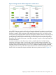
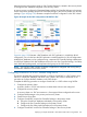
For 3DC operations, a package requires three different device groups. For Tri-Link configuration,
a package requires three different device groups: Continuous Access Synchronous or
Continuous Access journal device group between DC1 and DC2, Continuous Access
journal device group between DC1 or DC2 and DC3, and a Delta Resync device group from
either DC1 or DC2 to DC3 depending on where Continuous Access journal pair to DC3 is
configured.
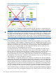
For Multi-Target Bi-Link configuration, a package requires three different device groups:
Continuous Access Synchronous or Continuous Access journal device group
between DC1 and DC2, Continuous Access journal device group between DC1 and DC3,
and a "phantom" device group between DC2 to DC3.
For Multi-Hop Bi-Link configuration, a package requires three different device groups: Continuous
Access Synchronous or Continuous Access journal device group between DC1 and
DC2, Continuous Access journal device group between DC2 and DC3, and a "phantom"
device group between DC1 to DC3.
130 Designing a Three Data Center Disaster Recovery Solution