
Building Disaster Recovery Serviceguard Solutions Using Metrocluster with Continuous Access for P9000 and XP A.11.00

Metrocluster environment file is automatically generated on all nodes when this package
configuration is applied in the cluster.
CAUTION: Do not delete or edit the Metrocluster environment file that is generated. This
file is crucial for 3DC operations.
Complete the following procedure on a node in the recovery cluster to configure a recovery package
using the 3DC modules:
1. Create a modular recovery package configuration file using the Metrocluster with Continuous
Access for P9000 and XP 3DC recovery module dts/recovery_xpca3dc along with the
required modules:
# cmmakepkg –m dts/recovery_xpca3dc pkgName.config
When deploying complex workloads, configure the Site Controller package as recovery
package and include dts/recovery_xpca3dc along with the dts/sc module:
# cmmakepkg –m dts/recovery_xpca3dc –m dts/sc pkgName.config
By default, the Metrocluster 3DC recovery module includes only the Serviceguard volume
group module. If other Serviceguard or Toolkit modules need to be included, they need to be
explicitly specified while creating the Metrocluster 3DC modular package configuration file.
2. Edit the following attributes in the pkgName.config file:
a. Specify the package directory for the dts/dts/dts_pkg_dir attribute:
dts/dts/dts_pkg_dir /etc/cmcluster/pkg
The Metrocluster Environment file is automatically generated for this package in this
directory.
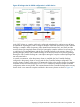
b. Specify the value for the 3DC_TOPOLOGY parameter based on the configuration used:
For Tri-Link configuration, specify Tri-Link:
3DC_TOPOLOGY Tri-Link
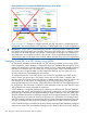
For Multi-Target Bi-Link configuration, specify "multi-target-bi-link":
3DC_TOPOLOGY multi-target-bi-link
For Multi-Hop Bi-Link configuration, specify "multi-hop-bi-link":
3DC_TOPOLOGY multi-hop-bi-link
c. Specify the DC1 nodes for the DC1_NODE_LIST parameter:
DC1_NODE_LIST “dc1_node1 dc1_node2”
d. Specify the DC2 nodes for the DC2_NODE_LIST parameter:
DC2_NODE_LIST “dc2_node1 dc2_node2”
e. Specify the DC3 nodes for the DC3_NODE_LIST parameter:
DC3_NODE_LIST “dc3_node1 dc3_node2”
f. Specify the device group configured between DC1 and DC2 for the
DC1_DC2_DEVICE_GROUP parameter:
DC1_DC2_DEVICE_GROUP dg12
g. Specify the device group configured between DC2 and DC3 for the
DC2_DC3_DEVICE_GROUP parameter:
DC2_DC3_DEVICE_GROUP dg23
This is a phantom device group when using Multi-Target Bi-Link configuration
h. Specify the device group configured between DC1 and DC3 for the
DC1_DC3_DEVICE_GROUP parameter:
DC1_DC3_DEVICE_GROUP dg13
This is a phantom device group when using Multi-Hop Bi-Link configuration
i. Specify the MU# used by the device group configured between DC1 and
DC2(DC1_DC2_DEVICE_GROUP) for the DC1_DC2_DEVICE_GROUP_MU parameter:
DC1_DC2_DEVICE_GROUP_MU <DG12_MU#>
124 Designing a Three Data Center Disaster Recovery Solution