
Building Disaster Recovery Serviceguard Solutions Using Metrocluster with Continuous Access for P9000 and XP A.11.00
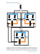
When Continuous Access Journal device group pair is configured between DC2 and DC3, the
data is replicated always in Multi-Hop topology from DC1. This configuration is called Multi-Hop
Bi-Link configuration.
In a typical customer DRS environment, more than one application is usually configured to be run
in a Metrocluster/Continentalclusters. Depending on the application distribution in a 3DC
environment, some applications can have Site 1 as its DC1. At the same time, some other
applications can have Site 2 as its DC1.
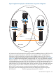
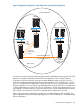
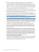
Figure 39 (page 105) depicts an example of two applications distributed in a DRS 3DC environment
balancing the server and replication load. In this example:
• Site 1 is the primary site or DC1 for the application A, and hot-standby site or DC2 for the
application B.
• Site 2 is the primary site or DC1 for the application B, and hot-standby site or DC2 for the
application A.
• Site 3 is the second-standby site or DC3 for both application A and B.
• The application A is configured using 3DC CAJ/CAJ replication. The application B is configured
using 3DC Sync/CAJ replication.
• For the application A, the data is replicated with Multi-Target Bi-Link configuration i.e. in a
Multi-Target topology from its DC1 to DC2 and DC3.
• For the application B, the data is replicated with Multi-Hop Bi-Link configuration i.e. in a
Multi-Hop topology from its DC1 to DC2 and then from its DC2 to DC3.
If there is a disaster at Site1, then the application A fails over to its DC2 i.e. Site2. In this scenario,
it is not possible to replicate the applications A and B data to DC3 using the existing application
Continuous Access journal pair configured between Site1 and Site3. As there is no Continuous
Access link between Site 2 and Site 3, it is not possible to replicate the application A and application
B data to DC3. Here the application data is not protected at DC3 upon a disaster at Site1. In this
scenario, the disaster tolerance to the applications A and B is lost. This is not the case with Tri-Link
configurations where Delta Resync pair is used to replicate data to DC3 in this kind of scenarios.
Overview of Device Group Monitor Feature in 3DC DR Solution
The Device Group Monitor (DGM) provides the capability to monitor the status of all the device
groups, used in a package configured in a 3DC environment, from the node where the package
is running. Based on Tri-Link or Bi-Link configuration, it monitors either three or two device groups
respectively. For example, if it is a Tri-Link configuration and the package is running on a node in
DC1, it monitors the status of all the device groups: DC1-DC2, DC2-DC3, and DC1-DC3 configured
in a package. If it is a Bi-Link configuration and the package is running on a node in DC1, it
monitors the status of DC1-DC2 device group and then either DC2-DC3 device group or DC1-DC3
device group based on whether the Active-CAJ pair is configured between DC2 and DC3 or
between DC1 and DC3 respectively.
The DGM provides the following functionalities:
• Sends a notification message upon the change in a device group status.
• Performs automatic resynchronization of the Continuous Access device group upon link
recovery.
• In case of a Tri-Link configuration, it performs automatic resynchronization of the Delta Resync
pair upon some of the failures that result in data not being replicated over the active Continuous
Access Journal pair to the third data center (DC3).
In the 3DC environment, where the device group state is not actively monitored, it may not be
apparent when the application data is not remotely protected for an extended period of time. For
example, there is a link failure between DC1 and DC2. If DGM is not configured, this link failure
may go unnoticed and this will cause data loss at DC2 upon DC1 failure. Similarly, for example,
106 Designing a Three Data Center Disaster Recovery Solution