
HP Integrity Virtual Server Manager 6.2 User Guide
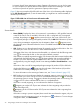
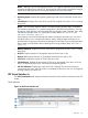
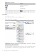
Table Of Contents
- HP Integrity Virtual Server Manager 6.2 User Guide
- Contents
- 1 Introduction
- 2 Installing Integrity Virtual Server Manager
- 3 Accessing and Navigating Integrity Virtual Server Manager
- 4 Using Integrity Virtual Server Manager views and tabs
- 5 Using Integrity Virtual Server Manager menus
- 6 Working with VMs or vPars
- Working with VMs
- Planning VMs
- Creating VMs
- Modifying VMs
- Starting VMs
- Stopping VMs
- Restarting VMs
- Deleting VMs
- Migrating VMs
- Suspending VMs
- Resuming VMs
- Moving suspend files
- Creating virtual switches
- Starting, stopping, and deleting virtual switches
- Deleting network or storage devices
- Opening iLO console
- Opening virtual iLO remote console
- Deleting virtual iLO remote console
- Deleting DIOs
- Adding DIOs
- Replacing DIO H/W path
- Replacing DIO MAC address
- Working with vPars
- Creating vPars
- Modifying vPars
- Booting vPars
- Stopping vPars
- Resetting vPars
- Creating virtual switches
- Starting, stopping, and deleting virtual switches
- Deleting network or storage devices
- Deleting vPars
- Opening iLO console
- Opening virtual iLO remote console
- Deleting virtual iLO remote console
- Adding DIOs
- Replacing DIO H/W path
- Replacing DIO MAC address
- Deleting DIOs
- Working with VMs
- 7 Collecting and viewing utilization data
- 8 Viewing logs and version information
- 9 Support and other resources
- Information to collect before contacting HP
- How to contact HP
- Security bulletin and alert policy for non-HP owned software components
- Subscription service
- Registering for software technical support and update service
- How to use your software technical support and update
- HP authorized resellers
- New and changed information in this edition
- Related information
- Typographic conventions
- 10 Documentation feedback
- A Error messages, status indicators, and troubleshooting
- Glossary
- Index
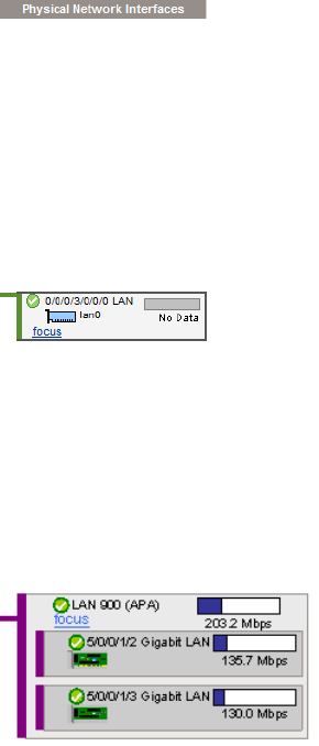
Physical Network Interfaces column contents
Each box in the Physical Network Interfaces column represents one of the following:
• A physical network interface card in the VSP
Figure 20 Physical network interface card
• An APA. When multiple physical network interface devices are aggregated using the Auto
Port Aggregation (APA) software package, they are displayed as network devices inside an
APA box.
Figure 21 APA
The icon next to the hardware path of the physical interface device shows whether the device is
operational.
The label next to the hardware path shows the description for the physical interface device.
The bar graph indicates network throughput, if available.
If the physical interface can support AVIO, the label Supports AVIO appears next to the Focus link.
The Focus link limits the display to the selected physical interface and anything connected to it. If
you use this link to focus on a specific physical interface, you can return to displaying all the
physical interfaces by using the Show All link visible on the focus page.
40 Using Integrity Virtual Server Manager views and tabs