
HP Insight Recovery Technical White Paper

4
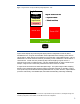
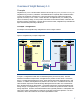
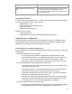
Figure 2.
Example of provisioning a new
logical server
Figure 2 illust
rates how a
logical server
can
be
provisioned
from a physical resource pool using
Insigh
t Dynamics
--
VSE
. The
logical server
can be created
using
Insight Dynamics
--
VSE
and
moved
to any compatible
resource
.
Once created, a
logical server
can remain as an inactive profile without
any defined reso
urces. The ability to reassign a
logical serv
er
profil
e
from one resource to another
requires
the
sharing of
server, networking, and storage
resources
--
inc
luding shared storage
for t
he
OS boot image,
application
software, and
application data.
This
sharing of compute resources is
fundamental to the
design of
Insight Dynamics
--
VSE
.
Disaster R
ecovery
C
oncepts
T
o protect against the disruptive impact of a large
-
scale disaster
on a data center’s compute
infrastructure
--
such as
fire
s, hurricanes
,
or
a broken water
pipe in the datacenter
--
DR
sol
utions
typically involve
failing over
application workloads
to a remote site.
The
method of
failover can range from automated solutions that are based on storage replication, to manual
solutions that involve restoring data and applications from off
line med
ia such as
backup
tape
s.
Recovery is
typically
performed at a remote site
–
usually
some geographic dist
ance away from the
primary site
--
ranging
from metropolitan (“m
etro”) area distances (
for example
tens to hundreds
of
miles) to
thousand
s of miles or a
cross continents
.
Whether manual or automatic, these solutions involve
the restoration of applications (also known as
“services”) and data associated with those applications within a “reasonable”
amount
of tim
e.
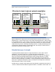
The
Node 3 Profile
MAC addresses
Network connections
FC WWNs
FC SAN connections
FC Boot parameters
Provision new logical server example
Virtual Connect
For Ethernet
And Fibre Channel
works across multiple stacked
enclosures
Customer Data Center Networks
SAN
LAN
pNIC
pNIC
HBA
pNIC
pNIC
HBA
Node 2 Boot LUN
Node 1 Boot LUN
Node n
Profile
SIM CMS
pNIC
pNIC
HBA
StorageWorks EVA
boot from SAN
Node 1 Profile
MAC addresses
Network connections
FC WWNs
FC SAN connections
FC Boot parameters
Node 2 Profile
MAC addresses
Network connections
FC WWNs
FC SAN connections
FC Boot parameters
pNIC
pNIC
HBA
pNIC
pNIC
HBA
Node 3 Boot LUN