
HP CloudSystem Matrix How-To Guide: ESXi Cluster Provisioning


4
The Virtual Connect Flex-10 Ethernet modules are configured as in the Virtual Connect FlexFabric Cookbook
(http://h20000.www2.hp.com/bc/docs/support/SupportManual/c02616817/c02616817.pdf) but without the
second interconnect for an active-active configuration. A shared uplink set, which is presented to the server as
separate networks, is defined to carry deployment/management (ESX console) and ESX vMotion traffic. Additionally,
a vNet network is defined to carry the multiple VLAN traffic of production networks that will be configured though
vCenter by the provided OO workflows to be presented to virtual machines.
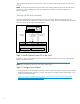
A shared uplink set is defined:
Bay 1, Port X1, and associated networks VMware Management and vMotion are added to the first shared uplink set
(in this example, VLAN-Trunk-1).
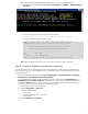
A vNet Ethernet network is defined, with VLAN tunneling enabled:
Bay 1, Port X2 is added to the first vNet (in this example, Trunk).
The corresponding ports in the external network switches are configured to support the appropriate VLAN IDs (in this
example, 101 and 102) for the shared uplink set associated networks (in this example, VMware Management and
vMotion) and the VLANs of the production networks (in this example, 2000, 2042, 2309, 2740, and 2936).
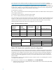
The following tables summarize the Virtual Connect configuration used in this example.
Table 1. Virtual Connect Ethernet networks
Ethernet
network
Enable
VLAN
tunneling
Shared uplink
set
External
VLAN ID
External uplink port
VMware
Management
VLAN-Trunk-1
101
vMotion
VLAN-Trunk-1
102
Trunk
Yes
Bay 2 Port X2
Table 2. Virtual Connect shared uplink sets
Shared uplink set
External uplink
port
Associated networks
Network name
VLAN ID
VLAN-Trunk-1
Bay 1 Port X1
VMware Management
101
(Infrastructure trunk)
vMotion
102
Matrix OE infrastructure operation network configuration
In this example, the Trunk network is configured in Virtual Connect as a VLAN tunnel trunk that carries production
VLANs with IDs 2000, 2042, 2309, 2740, and 2936. These VLAN networks are not defined in Virtual Connect
and therefore are not available in the IO network inventory. The network must first be created and designated as
carried on the VLAN tunnel trunk named Trunk. Alternatively, the production VLANs can be networks defined in
Virtual Connect and will be aggregated, as necessary, onto a single multinetwork port when the Virtual Connect
profile is created.
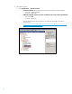
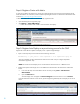
For each production network, perform the following steps to create the network in IO and designate it as carried
on
the VLAN trunk named Trunk:
If the network does not already exist on the IO Networks tab, click Create Network.
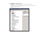
a. Specify the network name, network address/netmask, usable IP address space, Domain Name System (DNS),
and any other optional values.