
HP SureStore HD Server 4000 User's Guide - 5967-9979


11
-
34 Resolving Problems with Your Server
11. Use the Torx
®
#15 screws that you removed from the old server
module in step 3 on page 11-31, to secure the new server module
to the enclosure.
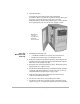
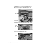
12. Inside the enclosure, find the white plastic power connector. (It is
the in-line connector on the power cable, not the connector at the
end of the power cable for the tape drive.) See the illustration
below. Attach that connector to the leftmost connector. labeled
“Power”, on the rear of the server module. It is keyed to fit only
one way.
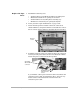
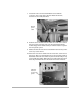
13. Attach the RJ-45 cable into the next connector, labeled “10/100”.
It is keyed to fit only one way.
14. Attach the serial cable into the next connector, labeled “Serial”.
It is keyed to fit only one way.
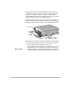
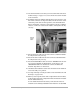
15. Attach the SCSI ribbon cable connectors: “
SERVER
TOP
” into the
top connector labeled “To Hard Drives” on the server, and
“
SERVER
BOTTOM
” into the bottom connector labeled “To
Internal Tape Drive” on the server.
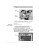
16. Check that the red button at the near end of the server module is
in its most fully “out” position.
17. Do steps 1 through 6 in the procedure “Close the Enclosure and
Start Up” on page 11-27.
18. When you start up the server with a replacement server module,
it will not have the same configuration that the old server module
had in its Flash memory.
A new module fresh from the factory will cause the server to
initialize as if it is being installed for the first time (as described
Plug in
power
cable