
Installing and Managing HP-UX Virtual Partitions (A.01.01)

Hardware Path to Physical I/O Slot Correspondence
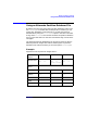
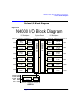
N-class I/O Block Diagram
Appendix A 119
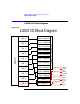
N-class I/O Block Diagram
Figure A-2
SBA 0
SBA 1
Slot 6
4 x PCI
Slot 5
4 x PCI
Slot 4
4 x PCI
Slot 3
4 x PCI
Slot 2
2 x PCI
Slot 1
2 x PCI
Slot 12
4 x PCI
Slot 11
4 x PCI
Slot 10
4 x PCI
Slot 9
4 x PCI
Slot 8
4 x PCI
Slot 7
4 x PCI
Slot 13
2 x PCI
LBA 2
LBA 10
LBA 8
LBA 12
LBA 4
LBA 5
LBA 10
LBA 12
LBA 4
LBA 2
LBA 8
LBA 0
LBA 0
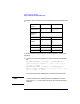
N4000 I/O Block Diagram
I/O Backplane I/O BackplaneSystem Board
Cabinet 00 Cardcage 01 Backplane 01 Cabinet 00 Cardcage 02 Backplane 02Cabinet 00 Cardcage 00
0/2/0
0/10/0
0/8/0
0/12/0
0/4/0
0/5/0
Cabinet 00 Cardcage 00 Backplane 00
10/100bt 0/0/0/0
ext SCSI 0/0/1/0
int SCSI 0/0/2/0
GSP 0/0/4/0
UPS 0/0/5/0
CORE I/O
1/0/0
1/8/0
1/2/0
1/4/0
1/10/0
1/12/0