
Implementing disaster recovery for HP Integrity Virtual Machines with Metrocluster and Continentalclusters on HP-UX 11i
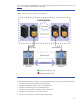

Table Of Contents
- Executive summary
- Introduction
- Audience
- Configuring Integrity Virtual Machines as packages in HP Metrocluster
- Verifying failover of Metrocluster packages across data centers
- Troubleshooting Metrocluster VM problems
- Application startup and monitoring
- Configuring Integrity Virtual Machines as packages in HP Continentalclusters
- Overview
- Software requirements for HP VMs in Continentalclusters
- Configuring HP VM packages in Continentalclusters
- Creating VM switches in all nodes of the primary cluster
- Configuring replicated storage for VM in Continentalclusters
- Installing the operating system on the virtual machine
- Testing the virtual guest OS in all nodes of the primary cluster
- Creating VM switches in all nodes of the recovery cluster
- Preparing the replicated storage for use in the recovery cluster
- Creating the virtual machine in all nodes of the recovery cluster
- Testing the virtual guest OS in all nodes of the recovery cluster
- Resynchronizing the replicated storage
- Packaging the HP VM in the primary cluster and the recovery cluster
- Creating a Continentalclusters package
- Creating a Continentalclusters configuration with the VM packages
- Running the Continentalclusters monitoring daemon in the recovery cluster
- Recovering to the recovery cluster
- Related documentation
- Appendix I
- Appendix II
- For more information
- Call to action

22
7. Create VM switches in all nodes of the recovery cluster.
8. Prepare the replicated storage for use in the recovery cluster.
9. Create the virtual machine in all nodes of the recovery cluster.
10. Test the virtual guest OS in all nodes of the recovery cluster.
11. Resynchronize the replicated storage.
12. Package the HP VM in the primary and recovery cluster.
13. Create a Continentalclusters configuration with the VM packages.
14. Run the Continentalclusters monitoring daemon in the recovery cluster.
An example configuration is explained with each of these steps to provide better understanding. The
following configuration is used in the example setup of HP VM in Continentalclusters. The HP VM
guest operating system is HP-UX 11i v3. The virtual disks used as backing store to create the virtual
machine are LVM volumes. The entire guest operating system image will be replicated to the recovery
cluster. The guest operating system will be configured with a static IP address.
Creating VM switches in all nodes of the primary cluster
In order to create a virtual switch, issue the following command on each node of the primary cluster:
#hpvmnet –c –S vs1 –n 0
where vs1 is the switch name and 0 is the LAN interface identifier. The above command will create a
vswitch over lan0 of the host.
Configuring replicated storage for VM in Continentalclusters
First, create replicated storage based on the type of the array. The steps required to create replicated
storage are explained in the chapters “Metrocluster with Continuous Access XP/P9000,”
“Metrocluster with Continuous Access EVA,” and “Metrocluster with EMC SRDF” of the Designing
Disaster Recovery Clusters Using Metrocluster and Continentalclusters user guide
, September 2010
(B7660-90028),
available at www.hp.com/go/hpux-serviceguard-docs (click on HP Serviceguard
Continentalclusters).
For the purposes of this example, a Continuous Access XP device group is created by the name
dgVM.
Configuring virtual storage over replicated storage
The supported types of backing stores are listed in this section’s overview.
The steps required to prepare the storage device for use as a backing store are explained in detail in
the chapters “Metrocluster with Continuous Access XP/P9000,” “Metrocluster with Continuous Access
EVA,” and “Metrocluster with EMC SRDF” of the Designing Disaster Recovery Clusters Using
Metrocluster and Continentalclusters user guide
, September 2010 (B7660-90028), available at
www.hp.com/go/hpux-serviceguard-docs (click on HP Serviceguard Continentalclusters).
For the purposes of this example, an LVM volume named “vgvm” and whole backing store replication
are considered. This means the entire backing store will reside in one Continuous Access XP device
group (dgVM) that was created in the previous step.
Creating the virtual machine in all nodes of the primary cluster
The HP VM command
hpvmcreate is used to create a virtual machine. Import the volume group vgvm
and issue the following command in each and every node in the primary cluster.
# hpvmcreate –Pcc_vm –a dvd:scsi::disk:/var/os/hpvm.0505_OE.Gold1.iso\
–a disk:scsi::lv: /dev/vgvm/rlvol1 \
–a network:lan:[hardware-address]:vswitch:vs1 \
–I cc_vm –O hpux