
Site Preparation Guide, Fifth Edition - HP Integrity Superdome and HP 9000 Superdome


Chapter 3
Electrical Specifications
Power Options
23
Step 5. Using the five screws retained from the removal procedure, replace the bottom panel on the PDCA.
Refer to Figure 3-5 on page 21 for panel installation details.
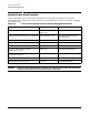
Step 6. To verify the proper wiring to a 4-wire PDCA, use a DVM to measure the voltage at the test points.
Voltage should read 200 - 240 Vac phase-to-phase as measured between the test points as follows:
L1 to L2, L2 to L3, L1 to L3.
IMPORTANT In some electrical distributions around the world, it is possible to measure 415 VAC
phase-to-phase. Ensure that your DVM is capable of measuring AC voltages of at
least 500VAC. A number of 5-wire power distribution systems may have
phase-to-phase voltages in excess of 400VAC. Many hand-held volt meters are
limited to 300VAC.
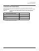
To verify the proper wiring to a 5-wire PDCA, use a DVM to measure the voltage at the test points.
Voltage should read 200-240VAC phase-to-neutral, as measured between the test points as follows:
L1 to N, L2 to N, L3 to N.
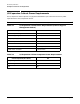
Figure 3-7 Cable Preparation Detail
NOTE Dimensions shown are for a cable strain relief without an extension nipple. If an extension
nipple is used, then the cable jacket must removed accordingly.
60
0.6 in
4.5 in
7.0 in
18 cm
11.5 cm
1.5 cm
1.5 cm
0.6 in
Ground Wire GN/YW