
NonStop NS16000 Series Planning Guide (H06.11+)

four, the remaining FCSAs and Fibre Channel disk modules can be configured in other
fault-tolerant configurations such as with two FCSAs and two Fibre Channel disk modules or
four FCSAs and three Fibre Channel disk modules.
• In systems with one IOAM enclosure:
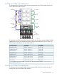
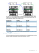
With two FCSAs and two Fibre Channel disk modules, the primary FCSA resides in
module 2 of the IOAM enclosure, and the backup FCSA resides in module 3. (See the
◦
example configuration in “NonStop Blade Element Group-Module-Slot Numbering”
(page 24).)
◦ With four FCSAs and four Fibre Channel disk modules, FCSA 1 and FCSA 2 reside in
module 2 of the IOAM enclosure, and FCSA 3 and FCSA 4 reside in module 3. (See the
example configuration in “Four FCSAs, Four FCDMs, One IOAM Enclosure” (page 97).)
• In systems with two or more IOAM enclosures
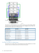
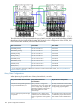
With two FCSAs and two Fibre Channel disk modules, the primary FCSA resides in IOAM
enclosure 1, and the backup FCSA resides in IOAM enclosure 2. (See the example
configuration in “Two FCSAs, Two FCDMs, Two IOAM Enclosures” (page 98).)
◦
◦ With four FCSAs and four Fibre Channel disk modules, FCSA 1 and FCSA 2 reside in
IOAM enclosure 1, and FCSA 3 and FCSA 4 reside in IOAM enclosure 2. (See the
example configuration in “Four FCSAs, Four FCDMs, Two IOAM Enclosures” (page 99).)
• Daisy-chain configurations follow the same configuration restrictions and rules that apply to
configurations that are not daisy-chained. (See “Daisy-Chain Configurations” (page 100).)
• Fibre Channel disk modules containing mirrored volumes must be installed in separate daisy
chains.
• Daisy-chained configurations require that all Fibre Channel disk modules reside in the same
cabinet and be physically grouped together.
• Daisy-chain configurations require an ID expander harness with terminators for proper Fibre
Channel disk module and disk drive identification.
• After you connect all Fibre Channel disk modules in configurations of four FCSAs and four
Fibre Channel disk modules, yet three Fibre Channel disk modules remain not connected,
connect them to the four FCSAs. (See the example configuration in “Four FCSAs, Three FCDMs,
One IOAM Enclosure” (page 102).)
Example Configurations of the IOAM Enclosure and Fibre Channel Disk Module
These subsections show various example configurations of FCSA controllers and Fibre Channel
disk modules with IOAM enclosures.
NOTE: Although it is not a requirement for fault tolerance to house the primary and mirror disk
drives in separate FCDMs. the example configurations show FCDMs housing only primary or mirror
drives, mainly for simplicity in keeping track of the physical locations of the drives.
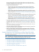
• “Two FCSAs, Two FCDMs, One IOAM Enclosure” (page 97)
• “Four FCSAs, Four FCDMs, One IOAM Enclosure” (page 97)
• “Two FCSAs, Two FCDMs, Two IOAM Enclosures” (page 98)
• “Four FCSAs, Four FCDMs, Two IOAM Enclosures” (page 99)
• “Daisy-Chain Configurations” (page 100)
• “Four FCSAs, Three FCDMs, One IOAM Enclosure” (page 102)
96 System Configuration Guidelines