
NonStop NS16000 Series Planning Guide (H06.11+)
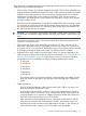
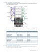
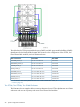
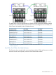

This table lists the FCSA group-module-slot-port (GMSP) and disk group-module-shelf-bay (GMSB)
identification for the factory-default system disk locations in the configuration of four FCSAs, four
Fibre Channel disk modules, and two IOAM enclosures:
Disk GMSB*FCSA GMSPDisk Volume Name
110.211.101110.2.1.1 and 111.2.1.1$SYSTEM (primary)
110.211.102110.2.1.1 and 111.2.1.1$DSMSCM (primary)
110.211.103110.2.1.1 and 111.2.1.1$AUDIT (primary)
110.211.104110.2.1.1 and 111.2.1.1$OSS (primary)
110.312.101110.3.1.2 and 111.3.1.2$SYSTEM (mirror)
110.312.102110.3.1.2 and 111.3.1.2$DSMSCM (mirror)
110.312.103110.3.1.2 and 111.3.1.2$AUDIT (mirror)
110.312.104110.3.1.2 and 111.3.1.2$OSS (mirror)
* For an illustration of the factory-default slot locations for a Fibre Channel disk module, see “Factory-Default Disk
Volume Locations” (page 94)
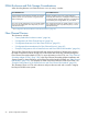
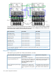
Daisy-Chain Configurations
When planning for possible use of daisy-chained disks, consider:
Requirements for Daisy-Chain
1
Daisy-Chained Disks Not
Recommended
Daisy-Chained Disks Recommended
All daisy-chained Fibre Channel disk
modules reside in the same cabinet and
are physically grouped together.
Many volumes in a large Fibre
Channel loop. The more volumes that
exist in a larger loop, the higher the
Cost-sensitive storage and applications
using low-bandwidth disk I/O.
potential for negative impact from a
failure that takes down a Fibre
Channel loop.
ID expander harness with terminators
is installed for proper Fibre Channel
disk module and drive identification.
Applications with a highly mixed
workload, such as transaction data
bases or applications with high disk
I/O.
Low-cost, high-capacity data storage
is important.
100 System Configuration Guidelines