
Site Preparation Guide, Third Edition - HP Integrity cx2600


General Site Preparation Guidelines
Electrical Factors
Chapter 3
25
Dual power sources might originate from two separate DC sources. Voltage potentials from ground pin to
ground pin of these sources should be measured and verified to be at or near 0.0 volts. Voltage levels that
deviate or are measured above 3.0 volts should be further investigated. Increased voltages might be
hazardous to personnel, and should be further investigated.
Cabinet Performance Grounding (High Frequency Ground)
Signal interconnects between system cabinets require high frequency ground return paths. Connect all
cabinets to site ground.
NOTE In some cases power distribution system green (green/yellow) wire ground conductors are too
long and inductive to provide adequate high frequency ground return paths. Therefore, a
ground strap (customer-supplied) should be used for connecting the system cabinet to the site
grounding grid (customer-supplied). When connecting this ground, ensure that the raised floor
is properly grounded for high frequency.
Power panels located in close proximity to the computer equipment should also be connected to the site
grounding grid. Methods of providing a sufficiently high frequency ground grid are described in the next
sections.
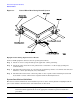
Raised Floor High Frequency Noise Grounding
If a raised floor system is used, install a complete signal grounding grid for maintaining equal potential over
a broad band of frequencies. The grounding grid should be connected to the equipment cabinet and electrical
service entrance ground at multiple connection points using a minimum #6 AWG (16mm2) wire ground
conductor. The following Figure 3-1 illustrates a metallic strip grounding system.
NOTE Regardless of the grounding connection method used, the raised floor should be grounded as an
absolute safety minimum.
HP recommends the following approaches:
• Excellent—Add a grounding grid to the subfloor. The grounding grid should be made of copper strips
mounted to the subfloor. The strips should be 0.032 in. (0.08 cm) thick and a minimum of 3.0 in. (8.0 cm)
wide.
Connect each pedestal to four strips using 1/4 in. (6.0 mm) bolts tightened to the manufacturer’s torque
recommendation.
• Better— A grounded #6 AWG minimum copper wire grid mechanically clamped to floor pedestals and
properly bonded to the building/site ground.
• Good—Use the raised floor structure as a ground grid. In this case, the floor must be designed as a ground
grid with bolted down stringers and corrosion resistive plating (to provide low resistance and attachment
points for connection to service entrance ground and HP computer equipment). The use of conductive floor
tiles with this style of grid further enhances ground performance. The structure needs to be mechanically
bonded to a known good ground point.