
Using ProLiant Essentials Rapid Deployment Pack for scripted blade based switch configuration
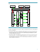
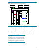
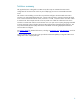
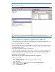

Figure 1. Initial interconnect switch configuration
Sw itch
A
BL20p
Bay 4
NIC 1
iLO
NIC 2
NIC 3
BL20p
Bay 5
NIC 1
iLO
NIC 2
NIC 3
Sw itch
B
Second Level Switch
RDP Server Red VLAN Client Blue VLAN Client
7
8
9
1
0
7
8
9
10
In Figure 2, the configuration is the same as in Figure 1, except the servers have now been deployed
with a new configuration.
• For the server in bay 4, the new configuration specifies that NICs 2 and 3 are to be placed on the
blue VLAN network (VID=10). As part of this server’s deployment, port 8 of both switch A and B
has been configured for the blue network. Port 7 for both switches (iLO and PXE NIC 1) remain in
the default management VLAN (VID=1).
• For the server in bay 5, the configuration specifies that NICs 2 and 3 are to be placed on the red
VLAN network (VID=11). As part of the blade B deployment, port 10 of both switch A and B has
been configured for the red network. Port 9 for both switches (iLO and PXE NIC 1) remain in the
default management VLAN (VID=1).
4