
Using ProLiant Essentials Rapid Deployment Pack for scripted blade based switch configuration


Text conventions
This HOWTO uses the following conventions to distinguish elements of text:
Menu options, Command names, Dialog box
names, Screen names
These elements appear in initial capital letters and may appear in
boldface for emphasis.
User input (commands to be typed)
User input appears in a different typeface
and is highlighted in gray.
Scripts and files
The content of the scripts and files appears
in a different typeface and is highlighted in
gray with a border around it.
Comments included in the scripts are listed
in blue font for explanation purposes and
marked with comment markers (#) so that the
code can be copied and pasted.
Problem description
When a server deployment is initiated, often the server’s network interface controllers (NIC) are
associated with specific switch ports that must be configured in specific VLANs. The server being
deployed cannot configure the switch; and as a result, a customer was required to log on to both
switches residing in the same enclosure as the server being deployed, and then configure the proper
switch ports manually.
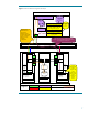
For example, assume that your current environment uses a ProLiant BL p-Class server blade enclosure
and deploys BL20p servers into one of the following configurations:
• Configuration 1: The iLO and NIC 1 (with PXE) ports are to be deployed on the management VLAN
(VID=1) and NIC 2 and NIC 3 are to be deployed on the production VLAN (for our example, we
will use VID=10).
• Configuration 2: This configuration is identical to the first configuration except that the production
VLAN uses VID=11.
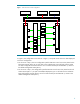
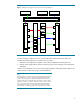
A ProLiant p-Class server blade enclosure is configured with the interconnect switches (switch A and
B) and two non-deployed BL20p servers installed in bays 4 and 5 (Figure 1). The server blade
enclosure is connected to a production network infrastructure that is configured with three VLANs:
green management VLAN (VID=1), blue production VLAN (VID=10), and the red production VLAN
(VID=11). An RDP for Windows deployment server (RDP Server) is connected to the management
VLAN. The interconnect switch rear external ports (uplinks) have been configured to participate in all
three VLANs (VIDs=1, 10, and 11). All other switch ports are in their factory default configuration.
Therefore, the interconnect switch ports connected to the servers (downlinks) are included only in the
default (management) VLAN (VID=1). With the interconnect switch in this configuration, the server
NICs are unable able to access the two production VLANs, VLAN 10 and VLAN 11, making it
impossible for these servers to access the production networks until the interconnect switch
configuration is configured properly for this example network.
3