
Using ProLiant Essentials Rapid Deployment Pack for scripted blade based switch configuration
When the RDP Windows Edition boot image is downloaded onto the server being deployed, it
returns the server’s rack, server blade enclosure, and bay ID to the RDP server. The RDP server
stores that data in its database. The location information can be retrieved from within a server-side
script by executing a specific set of commands. These specific server-side script commands place
the location information in environment variables that can be retrieved by a locally executed
program when executed within the same context.
2. Execute a local program to configure the interconnect switches.
This local program executes on the deployment server and communicates with both interconnect
switches. The preferred mechanism for remotely configuring the interconnect switches is through
the use of a scriptable Telnet client. The p-Class GbE2 switches and e-Class GbE/p-Class GbE
switches (version 2.0 and later) support command line interfaces that can be used for scripted
Telnet operation. Scripted Telnet is script execution to a remote device via a telnet connection to
that device. In the example solution Perl based Telnet scripting is used because it is easily
configured and accessible to most IT professionals.
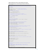
a. Using the rack and server blade enclosure identifiers from the previously created
environmental variables, the program obtains access information for the left and right
interconnect switches from a database created for this solution.
In order to connect with each interconnect switch, the switch IP and login information must be
known. The mechanism used in the example is to create a text file which relates a
rack/enclosure combination to the left and right interconnect switch host, user, and password
information. This text file needs to be generated prior to server deployment. If this mechanism
is used, set the access information for this text file to limit access to everything except the
interconnect switch configuration program.
b. Next, the program finds the interconnect switch port numbers associated with the server being
deployed from the server blade enclosure bay number.
Depending on which NICs need to be placed on specific VLANs, the bay number needs to be
mapped into the appropriate interconnect switch port numbers. Bay to port mapping varies: e-
Class interconnect switches have a different bay to port mapping than p-Class systems.
Additionally, within the p-Class system, BL20p and BL40p server NIC to interconnect switch
mapping will also vary.
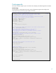
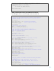
c. The program then logs onto the left interconnect switch using scripted Telnet. (The interconnect
switch access information is required as part of the logon process.)
The logon process is slightly different depending on the type of interconnect switch type used.
The interconnect switches also need to be configured to operate in a non-interactive mode.
See the code examples for an explanation how this is accomplished.
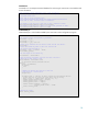
d. The program places the ports on the proper VLAN.
It executes the proper CLI commands to place the switch ports on the appropriate VLANs. The
CLI syntax is different between p-Class GbE2 and e-Class GbE/p-Class GbE.
e. Finally, the program repeats the last three steps for the side B switch. For e-Class switches, we
do not configure the B side switch.
Using an alternative to Perl
In order to customize a solution based on the provided example solution, a Win32 based program
capable of Telnet scripting must be used. While it is not the only option for users, Perl was used in the
example solution because it is widely accessible, easily configured, and commonly used in IT
environments. Other Win32 programs may be used, but have not been tested in this environment.
15