
Using ProLiant Essentials Rapid Deployment Pack for scripted blade based switch configuration
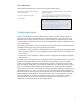
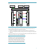
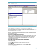

Figure 2. Updated switch configuration after the servers have been deployed
Switch
A
BL20p
Bay 4
NIC 1
iLO
NIC 2
NIC 3
BL20p
Bay 5
NIC 1
iLO
NIC 2
NIC 3
Switch
B
Network Infrastructure
RDP Server Red VLAN Client Blue VLAN Client
7
8
9
10
7
8
9
10
As in this example, to deploy servers into a ProLiant BL system with the interconnect switch, the
required approach had previously consisted of two main steps:
1. Automatic server deployment using RDP or other industry standard server deployment tool.
2. Manual switch configuration by directly connecting to each switch and typing in the appropriate
commands.
However, as an alternative, the new server-side scripting capability within RDP Windows Edition now
combines these two steps into a single, automated RDP job.
Note:
The labeling of the server NICs is performed by the operating system (OS).
The example shown in figures 1 and 2 is for the BL20p deployed with a
Windows operating system. For BL20p G2 deployed with a Windows
operating system, the OS labels the NICs connected to switch A as NIC 2
and NIC 3, and NIC 1 to switch B. Therefore in figures 1 and 2, Switch A
ports 7 and 9 would be connected to the BL20p G2 NIC labeled NIC 2
and ports 8 and 10 to NIC 3. For Switch B, ports 8 and 10 would be
connected NIC 1; no labeling change occurs to the iLO NIC on switch B.
5