
HP Insight Control Server Provisioning 7.3 Update 1 Installation Guide
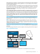
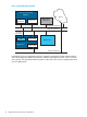
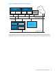
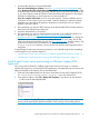
Table Of Contents
- HP Insight Control Server Provisioning 7.3 Update 1 Installation Guide
- Contents
- 1 Introduction/overview
- 2 Requirements and networking considerations
- 3 Installing your Insight Control server provisioning appliance for the first time
- Overview of the first time set up steps
- Get the software for a first time install
- Install Insight Control server provisioning on VMware vSphere/ESXi hypervisor
- Install Insight Control server provisioning on Microsoft Hyper-V hypervisor
- Log in to the appliance and configure appliance networking
- Accessing your appliance from a browser for the first time
- Next steps
- 4 Updating from version 7.2.2 to 7.3.1
- 5 DHCP server setup
- 6 Setting up the Media Server
- Introduction to the Media Server
- Introduction to the Insight Control server provisioning Media Server setup utility
- Requirements for setting up your Media Server
- Procedure for using the Insight Control server provisioning Media Server setup utility
- Changes made to your web server by Insight Control server provisioning Media Server setup utility
- 7 Generating and uploading WinPE to the appliance
- 8 Recommended actions after initial setup
- 9 Support and other resources
- 10 Documentation feedback
- A Updating from version 7.2 or 7.2.1 to 7.2.2
- Best practices for a successful update to 7.2.2
- Get the 7.2.2 update software and prepare it for use
- Prerequisites for update from 7.2/7.2.1 to 7.2.2
- Instructions for updating from 7.2 or 7.2.1 to 7.2.2
- What you need to do after installing the 7.2.2 update
- Changing from single NIC to multi-NIC (optional)
- Instructions for recovering from a failed 7.2.2 update
- REST API call to upload the 7.2.2 update file
- Glossary
- Index
When configuring your appliance, you have the option to have the Appliance IP and the Deployment
IP addresses sharing one network interface (Single NIC), or to use a separate network interface
for each IP address (Multi-NIC).
When configuring the appliance for Single NIC mode, use only the first NIC of your VM and leave
the second NIC disconnected. Since the Appliance IP and Deployment IP addresses will share the
first NIC, the IPs must be in the same subnet. The Deployment NIC must be able to access all of
the target servers and their iLOs either directly or through a router. See the figure below for a
Single NIC Mode Example.
When configuring the appliance in Multi-NIC mode, NIC1 is the Appliance NIC. It gets connected
to your management network and is the NIC you will browse to when accessing your appliance.
NIC2 is the Deployment NIC, and must have access to the Deployment NIC of all the target servers
either directly or through a router. In Multi-NIC mode, the Appliance IP and Deployment IP addresses
must be on different subnets, and under no circumstances should both NICs be connected to the
same network. See the figure below for a Multi-NIC Mode Example and a Multi-NIC Mode with
Matrix OE Example.
NOTE: In Multi-NIC mode, the appliance can access the iLOs through either the Appliance or
Deployment networks, depending on your requirements. No special configuration changes are
required for this.
NOTE: New Insight Control server provisioning appliances for version 7.2.2 come with two
network interfaces, however, if you are updating to 7.2.2 from a previous release, your original
appliance only had one NIC. If you wish to migrate to Multi-NIC mode see the online help topic
“Change from single NIC to multi-NIC”.
Once you have installed the Insight Control server provisioning appliance, see “Log in to the
appliance and configure appliance networking” (page 20) for details on how to configure appliance
networking.
The following diagrams illustrate the way the two appliance networking modes should be configured.
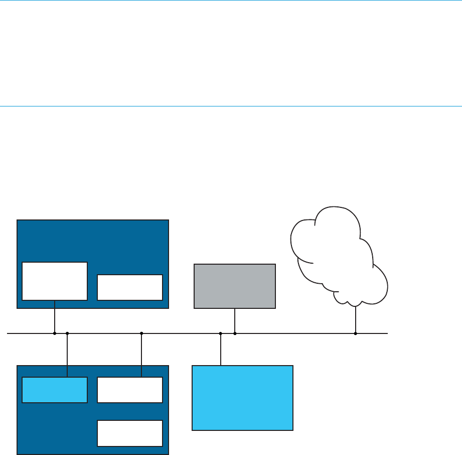
Figure 1 Single NIC Mode Example
IC server provisioning
Appliance
NIC 1
Appliance IP
Deployment IP
NIC 2
Not Used
Target Server
Single Network
NIC
Other NIC
NIC
Deployment NIC
iLO
Management
web browser
Media Server
Internet
In single NIC mode, all systems are connected to or are reachable from the one network.
Appliance networking considerations 11