HP Insight Control Power Management 7.0 User Guide Abstract This document describes the concepts of power management, provides information on managing power in your data center based on real-time user scenarios, lists troubleshooting information, and includes other additional information.
© Copyright 2004, 2012 Hewlett-Packard Development Company, L.P. Legal Notices Confidential computer software. Valid license from HP required for possession, use or copying. Consistent with FAR 12.211 and 12.212, Commercial Computer Software, Computer Software Documentation, and Technical Data for Commercial Items are licensed to the U.S. Government under vendor's standard commercial license. The information contained herein is subject to change without notice.
Contents 1 Introduction...............................................................................................5 Overview................................................................................................................................5 2 Key concepts.............................................................................................7 Data centers, racks, and power delivery devices...........................................................................7 Data centers........
Task: Task: Task: Task: Task: Task: Task: Task: Task: Controlling the power of the PDU outlets............................................................................27 Generating power topology for BladeSystem enclosures through iPDUs..................................27 Classifying systems by business criticality...........................................................................27 Defining rules to reduce power consumption .....................................................................
1 Introduction Overview HP Insight Control power management (power management) is a component of HP Insight Control to work on Windows, HP Insight Control for Linux to work on Linux, HP-UX 11i v3 Base Operating Environment to work on HP-UX, OpenVMS Base Operating Environment to work on OpenVMS, and NonStop System Console companion DVD to work on NonStop J-series operating system.
• Review CPU performance including the impact of power-saving technology. • Chart inlet air temperature for a single system, a group of systems, a single c-Class enclosure, a group of c-Class enclosures or a mix of the above systems. View a visualization of 24-hour peak temperatures across a data center floor, and within each rack. • Download historical data in CSV format to create customized reports.
2 Key concepts Data centers, racks, and power delivery devices Data centers HP Insight Control power management enables you to define the data center physical topology with racks containing systems, enclosures, and devices. A data center is an arbitrary rectangular grid that allows you to specify the placement of racks. You may create data centers to describe a lab floor or a portion of a computer room – that provides a useful grouping to summarize your environment and its power and thermal requirements.
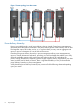
Figure 1 Power topology in a data center Power delivery hierarchy Power is provided through a set of power delivery devices. Insight Control power management represents places that can be monitored in the power delivery points of the hierarchy such as PDU load segment output, PDU outlet, and so on, or a place where you may want to aggregate and report on power consumption of a set of devices like servers.
Figure 2 Understanding Power Delivery Hierarchy • Power Feed: A top-level input of power from the data center facility into the power management-observable power infrastructure. • Breaker Panel: This represents the total group of breakers on a single Breaker Panel in a PDR. • Branch Circuit: This represents a single output of a PDR circuit breaker or power meter. • Rack PDU: Rack Power Distribution Unit - This represents the input power and multiple outputs to load segments.
3-phase Delta, and 3-phase Wye PDUs made up of 1-phase sub-circuits assuming the usage of the device is balanced.
required power and cooling capacity for the supported systems they contain. When the power and cooling capacity is interrupted or reduced, the consumption must be adjusted to match the change. Some examples of sudden capacity reduction include loss of external power, chiller failures, and utility company demands for cutbacks.
Use of management LAN HP recommends that all communications between the Systems Insight Manager CMS and the management processors be transmitted over a secure LAN isolated from the remainder of your network. This ensures SNMP data collection (which is inherently insecure) cannot be observed/monitored by other entities, and reduces the potential for external attacks on management processors by untrusted or compromised systems.
Power Regulator operates in four modes: • HP Static Low Power Mode. Power Regulator keeps the CPU in the lowest supported power state. This mode saves maximum resources, but it might affect system performance if processor utilization stays at or above 75% utilization. • HP Static High Performance Mode. Power Regulator keeps the CPU in the highest supported power state. This mode ensures maximum performance, but it does not save any resources.
The HP Power Regulator for Integrity modes are available on supported platforms equipped with Dual-Core Intel Itanium Processor 9100 series 1.6 GHz dual-core parts. Understanding HP Power Regulator savings Server power consumption savings from Power Regulator The resources saved by HP Power Regulator vary significantly from system to system, based on each system configuration and utilization. At higher utilization, Power Regulator saves more power.
The line graphs show that the power saved by HP Dynamic Power Savings Mode increases as the workload approaches 80% utilization. If the system is configured for HP Static Low Power Mode, it continues to save increasing amounts of power up to 100% utilization. The wider the gap between the red line and the blue or green line, the more power is saved. Analysis of throughput In the above figure, 1.
to avoid or even delay new data center expansion can save your company thousands of dollars.
Capping is online when the servers determine their maximum power consumption and will draw close to their maximum power at roughly the same time. If this peak is too large, it may cause problems. To prevent this from occurring, it is important to power on these server groups in a staggered manner.
3 Managing power and cooling facilities in your data center Task: Importing power configuration from third-party management software HP Insight Control power management provides tools to read data from third-party management software in the form of SQL or web services queries. For each power management supported third-party management software, a command is provided to generate output in the text format suitable for use by the ipmimport command.
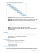
Figure 4 Power configuration information in a Microsoft Excel worksheet For a small data center, the data can be maintained manually in VIS format where a column in the Excel worksheet represents a rack and each cell is a slot position for a system. The VIS format is limited to only the physical hierarchy of the systems and devices in a data center. To convert data in the VIS format to text format, you can follow the instructions included in the ipmvis2txt man page.
Task: Monitoring the power and cooling requirements of your IT equipment With Insight Control power management, you can optimize the power and cooling requirements of your data center efficiently. While each individual system, enclosure, PDU, or PDR in your data center can provide its power requirements and sometimes even a limited amount of power consumption history, it is still difficult to understand the power and cooling requirements for your data center in a holistic way.
1. Specify the position of each system or enclosure in a rack. a. If you maintain a database (for example, UCMDB or Excel worksheet) describing the grouping of systems into racks and racks into a grid in a data center, you can import it directly into power management. For more information on importing information into power management, see Task: Importing power configuration from external databases. b.
Task: Ensuring the sufficient availability of power and cooling for your data center After configuring systems and devices in the data center, use the Power/Thermal Analysis page to view diagnostic information on the power and cooling infrastructure. In the Power/Thermal Analysis views page, • Power Status Alerts are highlighted with severity icons to highlight the severity of the alert. Alerts for contained devices are aggregated to the top-level object displayed.
5. Compare the Group Peak Power Consumption value with the available power calculated in as mentioned in step 3. Click Change in the Power Management Actions section and consider the following issues to determine if it is reasonable to power cap this group to the Available Power: a. The available power must be 10-20% above the Group Peak Power Consumption to ensure that there is sufficient cap headroom to enable future growth. b.
Task: Validating delivery of redundant power to systems After configuring the systems and devices, the Power Delivery tab in the Power/Thermal Analysis views page provides diagnostic information about power delivery redundancy to the devices on each power delivery device. By default, power management assumes that all devices must be configured for redundant power delivery, and displays a "Redundancy Error" message for any system for which there is no independent Side A & Side B power delivery.
While the enclosure may theoretically consume 35A of power (the Calibrated Max Power based upon the current configuration of the hardware), the maximum power observed since power management monitoring commenced was only 14A (Peak Observed Power). The difference of Calibrated Max Power and Peak Observed Power, 35A-14A = 21A, represents the potential power that can be reclaimed when applying the power cap value. Power caps are supported on both BladeSystem enclosures and many models of HP ProLiant servers.
5. Consider the business importance of the performance of an individual system before apply any cap that is significantly below the Calibrated Max Power. If the response time of the system is critically important, you must apply caps to other systems and ensure that your critical systems always have access to the absolute highest performance they can deliver.
1. 2. 3. 4. As the power demand varies, Enclosure Dynamic Power Capping can share caps between systems, it is the first place to investigate when capping and there is typically significant capacity that can be reclaimed by applying caps to enclosures. If you have multiple enclosures, reclaim similar percentages of capacity of the headroom from each enclosure instead of a large amount of headroom from a single enclosure.
Task: Defining rules to reduce power consumption HP Insight Control power management supplies pre-defined rules for reducing power consumption through the Data Center Power Control facility. To create rules specific to your environment, start with one of the pre-defined rules, customize it for your environment, and then mark it as "Ready for Use".
Task: Notification of Power Management Events Insight Control power management alerts are distributed as Systems Insight Manager events attributed to specific devices.
4 Troubleshooting Recovering from error messages Insight Control power management fails to show the Power graph and I receive the message Insight Control power management could not communicate with the Management Processor as it is not accessible. Solution: One of the following could be the reason for getting the above mentioned message. • Connection to Management Processor timed out due to network problem or Management Processor being unreachable.
Insight Control power management fails to show the Power graph and I receive the message Insight Control power management could not communicate with the Management Processor. Solution: Take the following steps to resolve the problem: 1. Make sure the Management Processor of the system is discovered in Systems Insight Manager. NOTE: 2. 3. System to iLO 2 association is a must to view the Power graph in power management.
Solution: Close the progress bar window. Provide the correct iLO credentials for the servers in the enclosure and try setting EDPC. When DCPC Shutdown rule is invoked on a managed node, the system does not shut down. When DCPC Shutdown rule is invoked on a managed node running on Windows Server 2003 SP2 (x64) operating system, the task is successful.
Configuring additional/optional requirements Unable to view/receive iLO 2 power threshold alerts. Solution: Perform the following to resolve the problem: • Using iLO 2 Web Interface, you need to configure the CMS server to receive SNMP alerts from iLO 2. • From Systems Insight Manager, you need to configure cpqHo2PowerThresholdTrap defined in cpqHost.mib on the SNMP Trap Settings (Options→Events→SNMP Trap Settings) page.
systems and devices is unable to yield power history data for some intervals of time due to various reasons: network problems, licensing issues, maintenance down time, etc. Solution: Check the status of these systems and devices. Power history construction takes an all or none approach. If there is missing data, power history is not calculated for the interval in time.
5 Support and other resources Information to collect before contacting HP Be sure to have the following information available before you contact HP: • Software product name • Hardware product model number • Operating system type and version • Applicable error message • Third-party hardware or software • Technical support registration number (if applicable) How to contact HP Use the following methods to contact HP technical support: • See the Contact HP worldwide website: http://www.hp.
Warranty information HP will replace defective delivery media for a period of 90 days from the date of purchase. This warranty applies to all Insight Management products. HP authorized resellers For the name of the nearest HP authorized reseller, see the following sources: • In the United States, see the HP U.S. service locator website: http://www.hp.com/service_locator • In other locations, see the Contact HP worldwide website: http://www.hp.
• HP ProLiant DL series servers: http://www.hp.com/servers/dl • HP ProLiant ML series servers: http://www.hp.com/servers/ml Typographic conventions This document uses the following typographical conventions: Book title The title of a book. On the web, this can be a hyperlink to the book itself. Command A command name or command phrase, for example ls -a. Computer output Information displayed by the computer.
A Capability matrix For using HP or third party non-managed or managed devices and servers, the available power management capabilities are given in the following table: Table 1 Insight Control power management capabilities Device Type Power Topology HP iPDU Intelligent Power Discovery Power ON/ OFF/ Locator UID CYCLE Control Automatic ✓ rack placement when following best-practice wiring strategy ✓ Power History Power Capping Power Rack/Power Capacity/ Planning Requirements 24-hour complete Autom
Glossary branch circuit This represents a single output of a PDR circuit breaker and the PDU to monitor the actual circuit power consumption. breaker panel This represents the total group of breakers on a single breaker panel in a PDR. calibrated max power Sum of the maximum theoretical power consumption of all attached devices. capacity The available or maximum power limit of the power delivery device. Central Management Server (CMS) Executes the Systems Insight Manager software.
Integrated Lights-Out (iLO) Basic system management functions, diagnostics, and essential Lights-Out functionality are included as core components of Integrated Lights-Out (iLO) supported systems. The standard features of iLO are referred to as iLO Standard. Advanced remote administration functionality, referred to as iLO Advanced, can be licensed with the optional Integrated Lights-Out Advanced Pack for HP Integrity Servers.
In this type of configuration, the term PDU often is loosely used to refer to the management module (since it is the named entity). power feed A top-level input of power from the Data center facility into the Power Management-observable power infrastructure. rack HP uses a universal rack to hold all supported rack mount hardware. Racks are measured in U height (each U being a slot). The most common size is 42U, but HP also sells 14U, 22U, 36U, and 47U racks. See http://www.hp.
Index C T concepts Data Center Power Control, 10 data centers, 7 Dynamic Power Capping, 16 Enclosure Dynamic Power Capping, 16 Power Capping, 16 power delivery devices, 7 power delivery hierarchy, 7 power history calculation, 7 power regulator, 12 power status alerts, 7 power summary meter, 7 power topology, 7 racks, 7 security properties, 11 task classifying systems by business criticality, 27 controlling the power of the PDU outlets, 27 defining rules for external events, 28 defining rules to reduce po