
HP StoreAll Storage Network Best Practices Guide
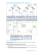
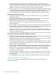
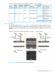
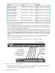
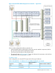
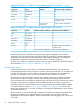
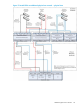
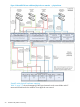
Table Of Contents
- HP StoreAll Storage Network Best Practices Guide
- Contents
- 1 Overview of HP StoreAll Storage networking
- 2 StoreAll 9730 platform networking
- 3 StoreAll 93xx/8x00 platform networking
- 4 Expanding an existing cluster
- 5 Support and other resources
- 6 Documentation feedback
- A BOND modes
- B StoreAll 93xx 10 GbE bonding modes and switch interconnection
- C Install and the default Virtual Connect configuration
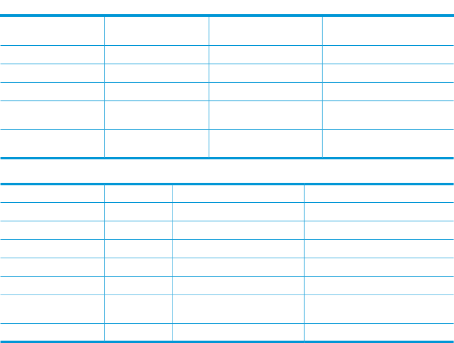
Table 10 StoreAll 9730 — IP addresses for one additional physical user network (continued)
Maximum number of addresses
Minimum number of
addressesSubnetComponent
88managementInterconnect
22managementOA module
11clusterFM VIF
Variable. At least 2 per node (32
included in total)
4userUser VIF
75 for maximum configuration33 for minimum
configuration
Table 11 StoreAll 9730 — IP addresses for two additional physical user networks
Maximum number of addressesMinimum number of addressesSubnetComponent
162user/clusterNodes
1616managementiLO
88managementInterconnect
22managementOA module
11clusterFM VIF
Variable. At least 3 per node (48
included in total)
6userUser VIF
91for maximum configuration35 for minimum configuration
Because of the manner in which the OA dynamically assigns the addresses to the enclosure
components, all of the enclosure bays must have addresses assigned for potential management
components even if the bay will not be populated in the shipped configuration. The enclosure
management IP addresses are assigned when the enclosure is initially configured.
Customer use of VLANs or multiple user network VIFs may require additional IP addresses beyond
those specified in Table 10 (page 47) and Table 11 (page 48).
Physical description
Adding a physical user network results in an additional bonded interface on the node and a
corresponding redundant set of connections to switches in the customer network. For one additional
network, the node gains a bond2 interface and two external connections. For two additional
networks, the node gains bond2 and bond3 interfaces and four external connections.
The physical connections from the enclosure to the customer networks are routed through either
the VC modules or the OA modules. Network traffic between the enclosure and the customer
network must traverse these modules to exit the enclosure. All other physical connections are routed
internally via the enclosure’s midplane. Network traffic between servers within an enclosure is
routed through the VC modules and does not count against the total external bandwidth availability.
To make the diagrams clearer, Figure 17 (page 49) and Figure 18 (page 50) do not show the
internal management and VC cross link connections. In the physical implementation, those internal
connections are present.
The VC modules are cross linked through connectors X7 and X8 to provide redundant paths from
the enclosure midplane to the external network. The connection of X7 and X8 is internally
implemented on the enclosure midplane. External cables should not be plugged into VC connections
X7 and X8.
48 StoreAll 9730 platform networking