
HP StoreAll Storage Network Best Practices Guide

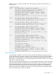
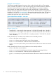


Table Of Contents
- HP StoreAll Storage Network Best Practices Guide
- Contents
- 1 Overview of HP StoreAll Storage networking
- 2 StoreAll 9730 platform networking
- 3 StoreAll 93xx/8x00 platform networking
- 4 Expanding an existing cluster
- 5 Support and other resources
- 6 Documentation feedback
- A BOND modes
- B StoreAll 93xx 10 GbE bonding modes and switch interconnection
- C Install and the default Virtual Connect configuration
Example node failover
The following example illustrates what occurs when a node is forced to fail over. The example
shows a StoreAll 9730 platform in a flat network topology. All IP addresses and other identifiers
have been chosen for illustration purposes and could be different on a customer installation.
In this example, the cluster starts with two active nodes. StoreAll node 1 has the active Fusion
Manager and is serving files from IP address 10.30.214.202. StoreAll node 2 is serving files from
IP address 10.30.214.203. Figure 4 (page 14) illustrates the initial state of this cluster. The interfaces
in bold (bond 0) are active on the StoreAll node, while the other interfaces are the standby
interfaces that have been put in place for failover.
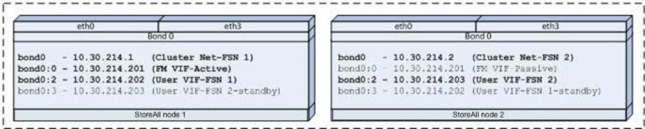
Figure 4 Node failover example — start state
In Figure 4 (page 14):
• StoreAll node 1 is servicing file client requests to 10.30.214.202 (StoreAll node 1–bond0:2).
• StoreAll node 2 is servicing file client requests to 10.30.214.203 (StoreAll node 2–bond0:2).
• Fusion Manager is active on StoreAll node 1, accepting requests to 10.30.214.201 (StoreAll
node 1–bond0:0)
Initially, StoreAll node 1 has three active interfaces and one standby interface:
• bond0 is the cluster network interface
• bond0:0 is a cluster network VIF for the active Fusion Manager
• bond0:2 is a user network VIF for file services from StoreAll node 1
• bond0:3 is not active, but has been provisioned for failover of file services duties from StoreAll
node 2
Initially, StoreAll node 2 has two active interfaces and two standby interfaces:
• bond0 is the cluster network interface
• bond0:0 is not active, but has been provisioned to support Fusion Manager failover.
• bond0:2 is a user network VIF for file services from StoreAll node 2
• bond0:3 is not active, but is provisioned for failover of file services duties from StoreAll node
1
14 Overview of HP StoreAll Storage networking