
User Manual - A3661-90001


7-20 SIMM Removal and Replacement
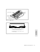
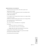
Figure 7-13 SIMM Installation
Memory
module
Connector
A. Position memory module above
connector so its notch is over
connector end nearest to the SP
board’s edge connector.
B. Insert module in connector so it angles
slightly toward the center of SP board.
C. Gently push top of module down
until it snaps into each locking tab.
CAUTION Do not force memory module into connector or against the
locking tabs. The notch at the end of the module prevents
incorrect installation.