
FW V06.XX/HAFM SW V08.02.00 HP StorageWorks SAN High Availability Planning Guide (AA-RS2DD-TE, July 2004)


Table Of Contents
- SAN HA Planning Guide
- Contents
- About this Guide
- Introduction to HP Fibre Channel Products
- Product Management
- Planning Considerations for Fibre Channel Topologies
- Fibre Channel Topologies
- Planning for Point-to-Point Connectivity
- Characteristics of Arbitrated Loop Operation
- Planning for Private Arbitrated Loop Connectivity
- Planning for Fabric-Attached Loop Connectivity
- Planning for Multi-Switch Fabric Support
- Fabric Topologies
- Planning a Fibre Channel Fabric Topology
- Fabric Topology Design Considerations
- FICON Cascading
- Physical Planning Considerations
- Port Connectivity and Fiber-Optic Cabling
- HAFM Appliance, LAN, and Remote Access Support
- Inband Management Access (Optional)
- Security Provisions
- Optional Features
- Configuration Planning Tasks
- Task 1: Prepare a Site Plan
- Task 2: Plan Fibre Channel Cable Routing
- Task 3: Consider Interoperability with Fabric Elements and End Devices
- Task 4: Plan Console Management Support
- Task 5: Plan Ethernet Access
- Task 6: Plan Network Addresses
- Task 7: Plan SNMP Support (Optional)
- Task 8: Plan E-Mail Notification (Optional)
- Task 9: Establish Product and HAFM Appliance Security Measures
- Task 10: Plan Phone Connections
- Task 11: Diagram the Planned Configuration
- Task 12: Assign Port Names and Nicknames
- Task 13: Complete the Planning Worksheet
- Task 14: Plan AC Power
- Task 15: Plan a Multi-Switch Fabric (Optional)
- Task 16: Plan Zone Sets for Multiple Products (Optional)
- Index
Physical Planning Considerations
150 SAN High Availability Planning Guide
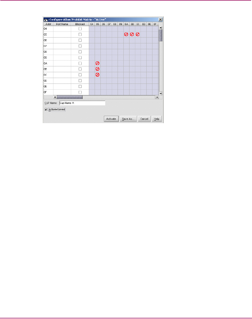
Figure 57: Configure Allow/Prohibit Matrix - Active Dialog Box
Figure 57 shows that port 1 (logical port address 05) is prohibited from
communicating with port 6 (logical port address 0A), port 7 (logical port address
0B), and port 8 (logical port address 0C).
When implementing an array that prohibits E_Port connectivity, be aware that
ISLs can be configured as unavailable to attached devices, causing complex
routing problems that can be difficult to fault isolate and be incorrectly diagnosed
as issues associated with the devices.
As an example of such a problem, refer to the simple two-director fabric
illustrated in Figure 58. As shown in the figure, ISL 1 connects Director A and
Director B through logical port addresses 09 and 1A. ISL 2 connects the directors
through logical port addresses 0A and 1B. A source server attaches to Director A
through logical port address 05. Two destination devices attach to Director B
through logical port addresses 2C and 2D.